If it jumps positive you need to switch the wires on the ammeter to make it go negative with horn blow. Amp gauge wiring 1 always disconnect the ground lead from the vehicle battery before wiring any gauge.

Digital Multi Panel Voltmeter Ammeter Hz Wiring With Diagram And Images Photoshop Cs5 Photoshop Adobe Photoshop
Stewart warner amp gauge wiring diagram valid voltmeter wiring diagram album diagrams wire center is just one of the many collections of sample.

Ammeter gauge wiring diagram. 2 classic instruments amp gauge should only be used on vehicles with alternators rated at 60 amps or less. The points at which the two wires connect to the solenoid to alternator cable are about 23 1 8 apart. Take your other piece of red 14 gauge wire and connect it to the other terminal of the ammeter.
It reveals the elements of the circuit as simplified forms and the power and signal connections between the devices. The amp gauge. It s easy to tell if you have the the wires correct on the ammeter.
Using an alternator with higher output capacity is dangerous and could cause a fire. A wiring diagram is a simplified traditional photographic representation of an electric circuit. Wire minimum with an insulation temperature rating of 220 f 105 c minimum from the battery terminal on the starter solenoid to the right terminal on the ammeter see wiring diagram.
Blow the horn and watch the needle jump. If you want to install an ammeter hook it up like one of the diagrams show. Regarding the sidebar in the latest issue of street rodder about ammeters versus voltmeters stewart warner.
Once you have connected it to the ammeter you will then connect it to the alternator terminal. 18 gage wire from fuel tank to gauge. If it jumps to the negative side you have it right.
Install an amp gauge in your car and you will instantly know the general condition of your vehicle s electrical system. With your positive battery terminal now connected to the ammeter you are ready to connect the next wire. Connect one end to terminal post on fuel level sender and the opposite end to the sender s terminal spade on back of gauge.
It shows the components of the circuit as simplified shapes and the faculty and signal friends amongst the devices. Connect ground wire from ground post on gauge to suitable chassis ground. Assortment of volt amp meter wiring diagram.
The yellow wire b coming from the charge side of the ammeter goes through the wiring harness and ties into the 10 awg cable which goes between the hot side of the starter solenoid and the alternator. Step 4 connect the ammeter to the alternator. Ammeter wiring diagram wiring diagram is a simplified good enough pictorial representation of an electrical circuit.
Also known as an ammeter this is one of the instruments that has largely been replaced with an idiot light. Ammeter tells you whether you re charging or discharging voltmeter. If a new hole is drilled in the firewall a grommet is recommended.
Without it you will not know there is a problem until it is too late.

Unique Wiring Diagram For Amp Gauge Diagram

Robot Check Volt Ampere Multimeter Diagram

Dc Ammeter Shunt Wiring Diagram L Fd8e3c77ca6fd112 Gif 1479 786 Car Amplifier Car Amp Diagram

Dune Buggy Wiring Diagram Wiring Diagram Vw Trike Diagram Dune Buggy

1 Wire Alternator Wiring Diagram Installation And Alternator Diagram Si Systems

Wire An Ammeter In A Hot Rod Wiring Diagram Schematics Diagram Ford Hot Rod Hot Rods

Pin De Maj En ولتمتر آمپرمتر Dc Ac Electricidad Y Electronica Electrotecnia Proyectos Electronicos

How To Wire Ammeter Elegant In 2020 Electrical Wiring Diagram Light Switch Wiring Diagram

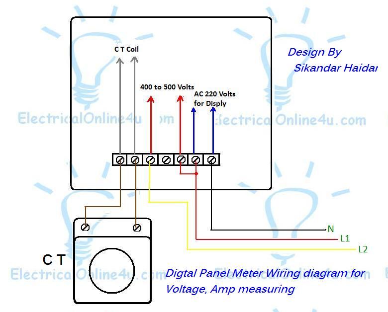
Digital Ammeter Wiring Diagram With Current Tramsformer Current Transformer Digital Ammeter Electrical Circuit Diagram

A Complete Guide Of Ammeter Selector Switch Wiring Diagram With Current Transformers And Ammeter Diagram Circuit Diagram Switch


