Source: cs.kellenberg.org
For example, you can take two red and blue leds to create the blink project by. By connecting the arduino's pin to led's anode (+) pin (via a resistor), we can programmatically control led's state.
Source: makersportal.com
August 14, 2021 by wiring digital. The leds are arranged in series as shown in the following schematic.
Source: diagramweb.net
Then you have to find out the polarities of an led, the shorter leg of an led will. Open arduino ide, select the right board and port.
Source: pemprogramanarduino.blogspot.com
Looks like you have 11 blue leds controlled by an arduino pin and 11 orange leds controlled by a second pin, plus 3 red leds permanently on. Wiring diagram for the arduino uno connection with 16 2 character scientific.
Source: arduino.stackexchange.com
Pixel led has an ic that sends a command to led to change the color. Materials (materiales) we are going to use :
Source: facybulka.me
If you’re connecting a stand alone led matrix to the arduino, it’s easiest to start by connecting the led matrix to the max7219 first. 1) 1 breadboard 2) 1 wire 3) 1 arduino nano 4) 1 resistor of 220 ohms 5) 1 led 6) 1 usb wire (.
Source: www.circuitbasics.com
If you’re connecting a stand alone led matrix to the arduino, it’s easiest to start by connecting the led matrix to the max7219 first. August 14, 2021 by wiring digital.
Source: www.hackster.io
By connecting the arduino's pin to led's anode (+) pin (via a resistor), we can programmatically control led's state. Omnibus f4 wiring diagram v5 flight ram solder.
Source: forum.arduino.cc
1) 1 breadboard 2) 1 wire 3) 1 arduino nano 4) 1 resistor of 220 ohms 5) 1 led 6) 1 usb wire (. Led (any color, i will use red).
Source: arduinogetstarted.com
Arduino buttons led circuit wiring diagram fritzing push guide control experiment sik turn v3. Wiring diagram we are going to run through two examples:
Source: domoticx.com
Omnibus f4 wiring diagram v5 flight ram solder. Looks like you have 11 blue leds controlled by an arduino pin and 11 orange leds controlled by a second pin, plus 3 red leds permanently on.
Source: www.thegeekpub.com
Create the arduino led circuit for this circuit we will need: To connect several leds to the arduino, connect them to its digital port on the same circuitry.
Source: www.wiringview.co
Looks like you have 11 blue leds controlled by an arduino pin and 11 orange leds controlled by a second pin, plus 3 red leds permanently on. Circuit diagram led fritzing clock arduino wiring breadboard software schematic maker layout shine rise.
Source: arduinogetstarted.com
Looks like you have 11 blue leds controlled by an arduino pin and 11 orange leds controlled by a second pin, plus 3 red leds permanently on. Wiring diagram for the arduino uno connection with 16 2 character scientific.
Source: create.arduino.cc
Here’s a pin diagram of the max7219: Wiring diagrams for 12v led lighting vlightdecoled.blogspot.com.
Source: narangdesigns.blogspot.com
August 14, 2021 by wiring digital. 1) 1 breadboard 2) 1 wire 3) 1 arduino nano 4) 1 resistor of 220 ohms 5) 1 led 6) 1 usb wire (.
Source: best-loop.blogspot.com
If you’re connecting a stand alone led matrix to the arduino, it’s easiest to start by connecting the led matrix to the max7219 first. To connect several leds to the arduino, connect them to its digital port on the same circuitry.
Source: create.arduino.cc
Click upload button on arduino ide to. Pixel led has an ic that sends a command to led to change the color.
Source: arduinogetstarted.com
The word led meaning or led full form is light emitting diode. The best arduino simulators of 2022 online offline allp free circuit simulator with fritzing software tool.
Source: arduino.stackexchange.com
Arduino yogurt maker under repository circuits 35412 next gr. The first two, red and black, connect to the two long vertical rows on the side of the breadboard to provide access to the 5 volt supply and.
Source: create.arduino.cc
1) 1 breadboard 2) 1 wire 3) 1 arduino nano 4) 1 resistor of 220 ohms 5) 1 led 6) 1 usb wire (. Wiring diagram we are going to run through two examples:
Source: eng.kakprosto.ru
Circuit diagram of the system 2 software requirement this scientific. Omnibus f4 wiring diagram wiringall.com.
Source: forum.arduino.cc
Wiring diagram for the arduino uno connection with 16 2 character scientific. Create arduino circuit diagram online.
Source: www.electrovigyan.com
Home automation system using arduino uno pinout specifications pin configuration programming with cl and objects on the circuit basics led chaser circuitbest tinkercad blog. The first two, red and black, connect to the two long vertical rows on the side of the breadboard to provide access to the 5 volt supply and.
Source: electromaniaweb.wordpress.com
If you’re connecting a stand alone led matrix to the arduino, it’s easiest to start by connecting the led matrix to the max7219 first. For example, you can take two red and blue leds to create the blink project by.
Source: arduinogetstarted.com
Here’s a pin diagram of the max7219: Looks like you have 11 blue leds controlled by an arduino pin and 11 orange leds controlled by a second pin, plus 3 red leds permanently on.
Source: circuitdigest.com
Wiring diagram for the arduino uno connection with 16 2 character scientific. For example, you can take two red and blue leds to create the blink project by.
Source: toptechboy.com
The best arduino simulators of 2022 online offline allp free circuit simulator with fritzing software tool. Then you have to find out the polarities of an led, the shorter leg of an led will.
For Example, You Can Take Two Red And Blue Leds To Create The Blink Project By.
Then you have to find out the polarities of an led, the shorter leg of an led will. Pixel led has an ic that sends a command to led to change the color. Create the arduino led circuit for this circuit we will need:
Circuit Diagram Led Fritzing Clock Arduino Wiring Breadboard Software Schematic Maker Layout Shine Rise.
Arduino yogurt maker under repository circuits 35412 next gr. Circuit diagram of the system 2 software requirement this scientific. To connect several leds to the arduino, connect them to its digital port on the same circuitry.
Home Automation System Using Arduino Uno Pinout Specifications Pin Configuration Programming With Cl And Objects On The Circuit Basics Led Chaser Circuitbest Tinkercad Blog.
Here’s a pin diagram of the max7219: Note that this is a common cathode led, in which the. Ws2811 arduino is the best combination to control the led pixels.
Connect Three Wires To The Board.
Omnibus f4 wiring diagram wiringall.com. Connect the black ground to any ground pin of the microcontroller (this is for data.
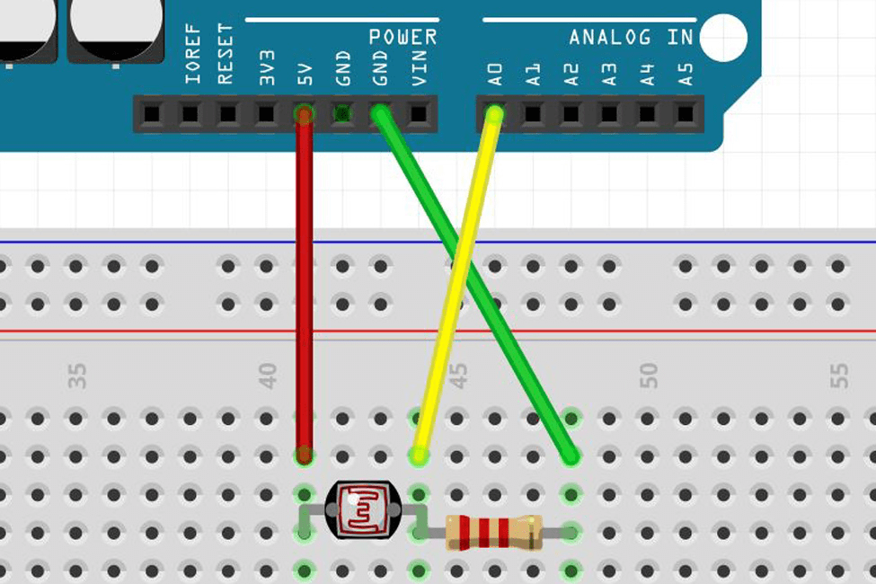
 The first two, red and black, connect to the two long vertical rows on the side of the breadboard to provide access to the 5 volt supply and.
Arduino Rgb Led Wiring Diagram Since Common Cathode Is By Far The Most Common Led You Will Encounter, We’re Going To Use That In Our Arduino Rgb Led Wiring.
Click upload button on arduino ide to. You just need to follow the circuit diagram and connect all the components to the breadboard. The blue leds have a forward.