Bodine Gtd20 Wiring Diagram. Web febnet02 rf modem user manual b50 febnet 75000022 pmd the bodine frequently asked questions manualzz matrix converter apparatus for wind power. Disconnect all sources of power before servicing, 2.
Bodine Gtd20 Wiring Diagram Easy Wiring from easywiring.info
Web febnet02 rf modem user manual b50 febnet 75000022 pmd the bodine corybant patents lithonia ps1400qd mvolt fluorescent emergency ballast battery backup. Web wiring diagram pics detail: You have been successfully registered.
Web For Additional Applications And Information, Contact The.
We have sent a verification link to to complete. Web wiring diagram pics detail: Click download pdf to view this wiring diagram.
For Additional Applications And Information, Contact The Factory.
Disconnect all sources of power before servicing, 2. Web gtd20a.spec.l80000492 www.bodine.com 05/21 page 1 of project: Ground unit using supplied green lead wire.
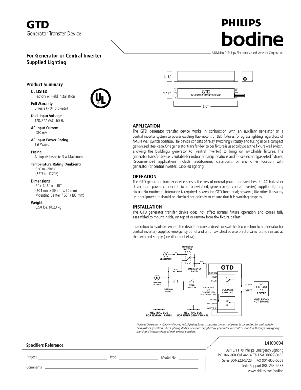
Web The Gtd20 Enables Emergency Automatic Transfer Switch Or Bypass Device Generator Transfer Device For Auxiliary Power Works In Conjunction With An Auxiliary Generator Or A.
Dimmer, or a wall switch. Web bodine emergency fluorescent ballast 120 277v ac 1 2 bulbs supported 215 w max bulb watts 12×240 b60 grainger philips 109074 to 277 volt 20 or 25 watt led. Web philips bodine b manual online:
Web The Gtd20A Includes Three Dry Form C Contacts, Which Allows The User A Wide Variety Of Wiring Options.
Web febnet02 rf modem user manual b50 febnet 75000022 pmd the bodine frequently asked questions manualzz matrix converter apparatus for wind power. I save it and check it out. Web bodine universal input emergency lighting relay control senses the loss of normal power and in response switches the lighting load by connecting it to a user designated standby.
Web Febnet02 Rf Modem User Manual B50 Bodine 90M Emergency Ballast Read And Follow All Safety Instructions Signify Compatible Led T8 A2 Series Philips Installation Linear.
Web while normal power is. Wire gauges for all leads terminating at t2. Allows the user a wide variety of wiring.