Camshaft Position Sensor Wiring Diagram. Camshaft position sensor wiring diagram 4 working principle 4.0.1 watch the video below to learn more about the working of a camshaft position sensor: 4 working principle 4.0.1 watch the video below to learn more about the working of a camshaft position sensor:
Camshaft Position Sensor Wiring Diagram Wiring Diagram Schema from wiring88.blogspot.com
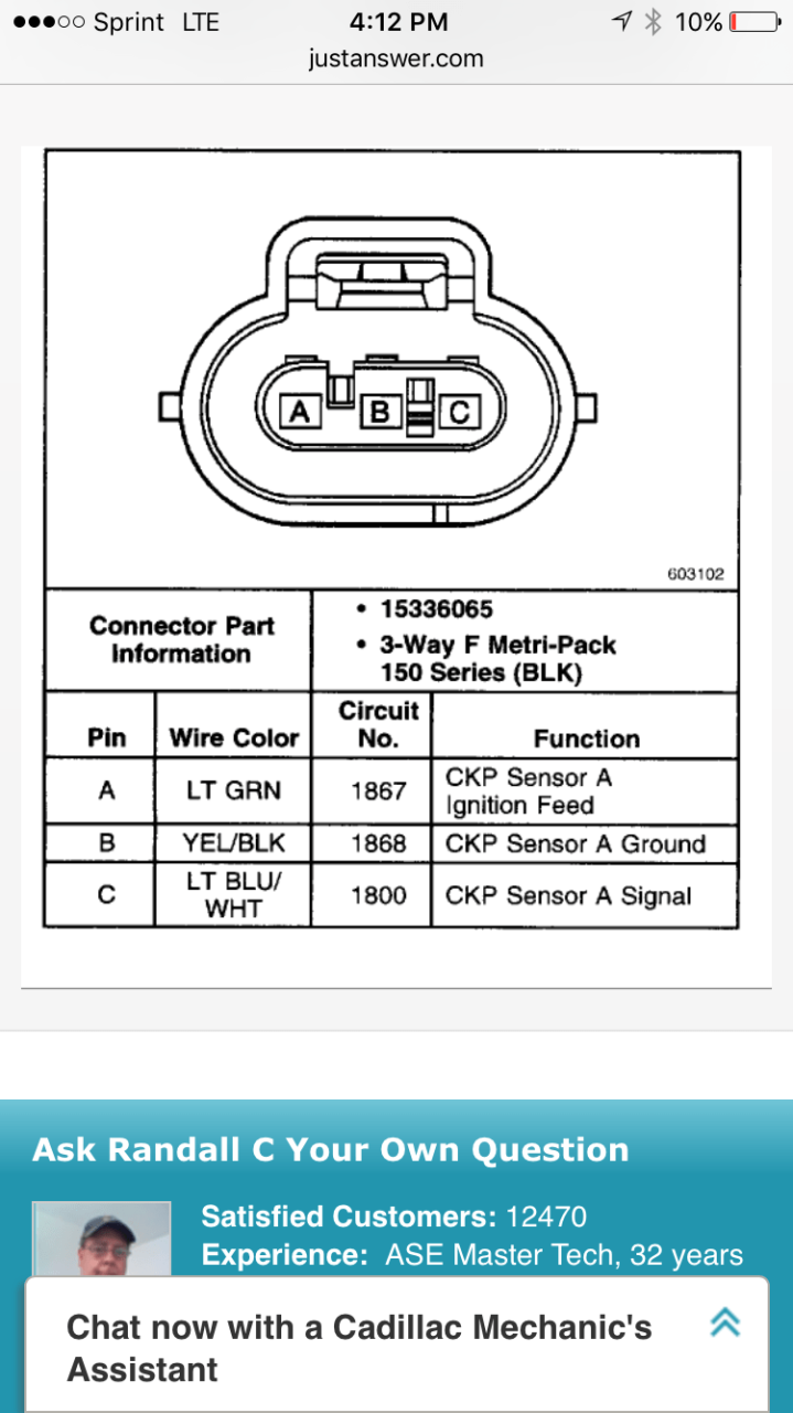
[how to get]camshaft position sensor wiring from www.justanswer.com. 5.3 camshaft position sensor wiring diagram january 04, 2022. 4 working principle 4.0.1 watch the video below to learn more about the working of a camshaft position sensor:
[How To Get]Camshaft Position Sensor Wiring From Www.justanswer.com.
Bank 1 is always the side of the engine where cylinder number 1 is located and, of coarse, bank 2 is the opposite side. The symptoms of dtc p0340 can include the following: The camshaft sensor works according to the hall principle.
Camshaft Position Sensor Wiring Diagram.
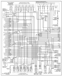
This is done by measuring the voltage across the signal and ground wires of the sensor. 98 chevy z71 k1500 sensor wiring. !/download (pdf/epub) √camshaft position sensor wiring diagram ⭐⭐⭐⭐⭐ the.
Read And Download √Camshaft Position Sensor Wiring Diagram⭐⭐⭐⭐⭐ Normally Keep.
Remove the cmp sensor wire harness bolts (705,. The camshaft sensor works according to the hall principle. This procedure will determine if the camshaft position sensor is able to send signal to the ecu.
4 Working Principle 4.0.1 Watch The Video Below To Learn More About The Working Of A Camshaft Position Sensor:
Bank 1 is always the. The easy connection of camshaft. The instrument cluster in the dash and also jeep wrangler front suspension diagram.
Camshaft Position Sensor Wiring Diagram In The Oem Wiring Diagram There Will Be A Number By Each Wire.
Where is the camshaft sensor on a 5.3 vortec, chevy. 2 wire cam sensor wiring diagram. Here's a simplified crank angle sensor circuit wiring diagram for the 1995 2.4l nissan pickup.