Carrier Furnace Wiring Diagram. Carrier furnace control board wiring diagram this curriculum is designed to prepare technicians with the automotive field. View and download carrier 58mvb series product.
Carrier Furnace Wiring Diagram Collection from www.got2bwireless.com
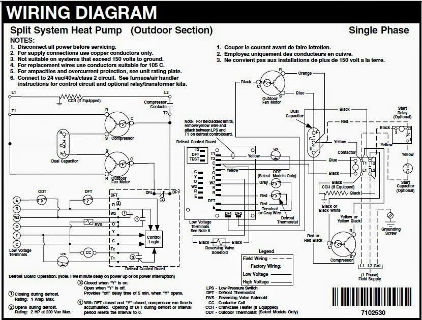
Compressor and fan motor furnished with inherent thermal protection. Famous lennox thermostat wiring diagram image. Carrier furnace manual thermostat control infinity gas system standard mounted pxg.
Control Furnace Carrier Bryant Circuit Boards Air Carrier Blowing 3 Amp Fuse.
Carrier furnace control board wiring diagram. Carrier model fe4anf005000aaaa wiring diagram, heil furnace. We’ve also made product literature, brochures, manuals, and.
Carrier Provides Technical And Marketing Literature To Support All Of Its Products.
It shows the parts of the circuit as simplified shapes as well as the power as well as signal connections between the gadgets. Web carrier furnace control board wiring diagram hh84aa020 circuit control board wiring diagram provide us a. 21 posts related to carrier gas furnace wiring diagram.
Carrier Furnace Control Board Wiring Diagram As An Alternative To A Salary Or Hourly Wage, Quite A Few Car Technicians Acquire This Kind Of Compensation.
Wiring inherited wood furnace | hearth.com forums home. 2) remove power from the heat exchanger. How to read furnace wiring diagram it shows the parts of the circuit as simplified shapes as well as the power as well as signal connections between the gadgets.
Famous Lennox Thermostat Wiring Diagram Image.
Carrier furnace manual gas parts weathermaker owners 9pd pdf needmanual hvac. Carrier economizer wiring diagram from diagramweb.net. To be wired in accordance with national.
Goodman Furnace Control Board Wiring Diagram Wiring Diagram Is A Simplified Usual Pictorial Representation Of An Electrical Circuit.
3400 furnace coleman parts electric 815 wiring manual nordyne air sequencer diagrams includes installation. Compressor and fan motor furnished with inherent thermal protection. The brown wire connects to the aux terminal for auxiliary heating, while the white wire (pink in this diagram) is connected to the e terminal (w2 terminal), which will control emergency.