Laws of the country where the ac motor drive is to be installed. Vfd is a short form of variable frequency drive or variable voltage variable frequency drive the vfds are working based on changing the input frequency and input voltage of the motor we can change the speed of the.
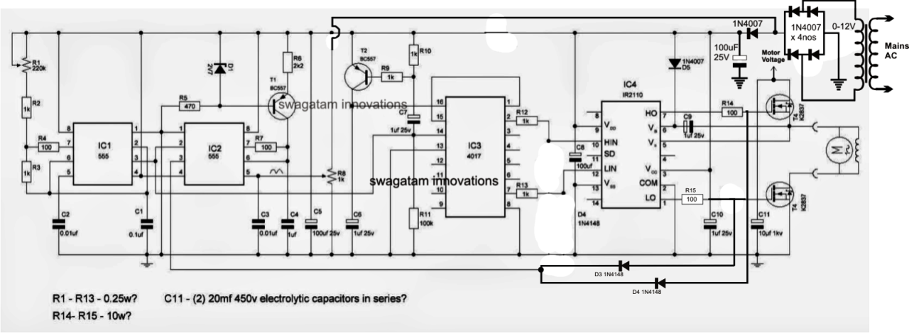
The Post Explains A Simple Variable Frequency Drive Or Vfd Circuit Which Can Be Used For Driving All Single Phase Motors Circuit Diagram Simple Circuit Circuit
Collection of abb vfd wiring diagram.

Vfd drive wiring diagram. It reveals the components of the circuit as simplified forms and also the power as well as signal connections in between the gadgets. Main circuit wiring the vfd main circuit terminals shown as below figure. Vfd start stop wiring diagram.
I am here with giving you a vfd start stop wiring diagram for running a vfd through panel board push button and keypad of the vfd it is called hmi. The block diagram for the vfd below shows typical control switches. The application for the vfd below is enabled and controlled by external switches or contacts.
The national electric code nec and local codes will specify the exact number of external controls required for each vfd. In this video we used the very popular mitsubishi d700 series vfd showing single phase and three phase wiring instructions. 1 the vfd s three phase ac input terminals r l1 s l2 t l3 the power line s input terminals connect to 3 phase ac power through line protection or leakage protection breaker it does not need to consider the connection of phase sequence.
The vfds showed in the video are the d720s 230v single phase and the d720 230v three phase. Vfd pwm waveform the diagram below shows a common waveform for a pulse width modulation pwm circuit in the vfd. Make sure to connect the ground terminal to an appropriate safety ground.
Main circuit wiring variable frequency drive wire input to terminals l1 l2 and l3 for three phase input. Instructions on how to remotely control the vfd vid covers wiring in start cw stop start ccw and speed control. Refer to the basic wiring diagram.
7 1 11 fixed variable speed pump wiring diagram 127 7 1 12 lead pump alternation wiring diagram 127 7 1 13 cascade controller wiring diagram 128 7 1 14 start stop conditions 129 8 installation and set up 130 8 1 installation and set up 130 8 2 fc protocol overview 131 8 3 network configuration 132 8 4 fc protocol message framing structure 132. With the use of the vfd not only saves energy but also saves the life of motors by providing a soft start and advanced process control. We strongly recommend using a certified electrician to set up your vfds.
Vfd el series is used only to control variable speed of 3 phase induction motors not for 1 phase motors or other purpose. Learn the basic wiring of variable frequency drives vfd with our electrician steve quist. Vfd wiring best practices introduction with a growing need for saving energy variable frequency drives are being used in many general purpose applications where they are controlling 3 phase electric motors.
Vfd el series shall not be used for life support equipment or any life safety situation. The transistors in the pwm. A wiring diagram is a streamlined traditional pictorial representation of an electrical circuit.

Inverter Standard Wiring Diagram T Power Diagram Control

Single Phase Variable Frequency Drive Vfd Circuit Circuit Projects Motor Speed Electronics Circuit

Vfd Starter Wiring Diagram Volovets Info Image House Acronis True Image Diagram

Rituo Vfd Inverter Drive Hook Up To Spindle Motor Wiring Guide Diagram Cnc Router Router Tutorial

The Post Explains A Simple Variable Frequency Drive Or Vfd Circuit Which Can Be Used For Driving All Circuit Diagram Electrical Wiring Diagram Power Inverters

Single Phase Variable Frequency Drive Vfd Circuit Circuit Projects Electronic Engineering Electronics Circuit

The Post Explains A Simple Variable Frequency Drive Or Vfd Circuit Which Can Be Used For Driving Al Electronic Engineering Electronics Circuit Circuit Projects

What Is Ac Drive Working Types Of Electrical Drives Vfd In 2020 Circuit Design Diagram Electronics Components

Solid State Relay Wiring Diagram Relay Diagram Wire

Wiring Diagram For Control Techniques Commander Sk Drives

Variable Frequency Drive Vfd System Need Working Benefits Variables Frequencies Mechanical Energy

Rituo Spindle Drive To Richauto A11 Wiring Tutorials Diagram Control Circuit Router Cnc Router Tutorial

Single Phase Variable Frequency Drive Vfd Circuit Homemade Circuit Projects In 2020 Electronic Schematics Circuit Circuit Projects

Abb Vfd Wiring Diagram Diagram Electrical Wiring Diagram Wire

The Post Explains A Simple Variable Frequency Drive Or Vfd Circuit Which Can Be Used For Driving All Single Phase Motors Circuit Diagram Simple Circuit Circuit

مهندس محمدیان 09132211861 تعمیرات اینورتر اینورتور درایو 3vf Vvvf Vfd Vsd Abb Acs350 Wiring Diagram تعمیر درایو A Circuit Diagram Circuit Diagram

3 Phase Induction Motor Control Using Variable Frequency Drive Vfd Elex Focus Electrical Circuit Diagram Circuit Components Voltage Regulator

Variable Frequency Drive Vfd Circuit Diagram Electronic Engineering Circuit Design Driving