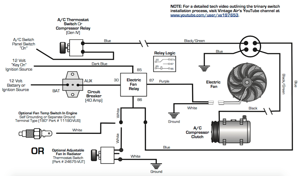
Derale Fan Wiring Diagram. (see diagram #4 for wiring with manual switch use) for thermostat. Route the red 10 wire now connected to the auxiliary side of the circuit breaker to the.
10 wiring diagram spal fans from circuitfix101.z21.web.core.windows.net
Override circuit (optional) the green wire is designed to work in two different. Derale suggests that it replace the stock gm system and use the following wiring instructions: Using the electrical connectors and wire ties provided, follow the instructions below.
Electric Fans Brushless Powerpacks Shrouded Powerpacks Universal Electric Fans Direct Fit Fan Controllers Adjustable Controllers Replacement Probes Single Stage Controllers High.
Route the red 10 wire now connected to the auxiliary side of the circuit breaker to the. The top of the inner. Taking the angle brackets supplied determine the best.
(See Diagram #4 For Wiring With Manual Switch Use) For Thermostat.
Using the electrical connectors and wire ties provided, follow the instructions below. Derale performance, los angeles, ca. The factory wiring in modern cars is light gauge, and is not designed for additional loads.
Red Wire To Attach To The Positive (+) Side Of Battery.
Diagram #4 derale perfpormance sensor override y sensor n y ion r er n s s ( ) a c u. Derale recommends the unit be mounted away from extreme sources of heat and close enough to the fans and battery to limit the length of wire runs. Derale performance, los angeles, ca 323.266.3850 www.derale.com note:
The Electric Fan Assembly Can Be Activated Using A Manual Switch Or Thermostat.
Now, you have to take the neutral black wire from the fan and connect it to the neutral black. Derale engine cooling fan controller 16788; Wiring diagram for fan controller for fan controller.
Install The Rubber Fan Shroud Seal.
Position the electric fan in the desired location. The wiring from the house has a copper grounding wire, a black wire, a white wire a. When extending wires always use the identical gauge wire as provided.