Digital Timer Switch Wiring Diagram. The 555 timer starts timing when switched on. Web 12v time delay relay circuit electroschematics com relays explained the engineering mindset programmable timer 8 input output 24v dc ato siemens 3rp1505.
Wiring Diagram For Intermatic Timers from schematron.org
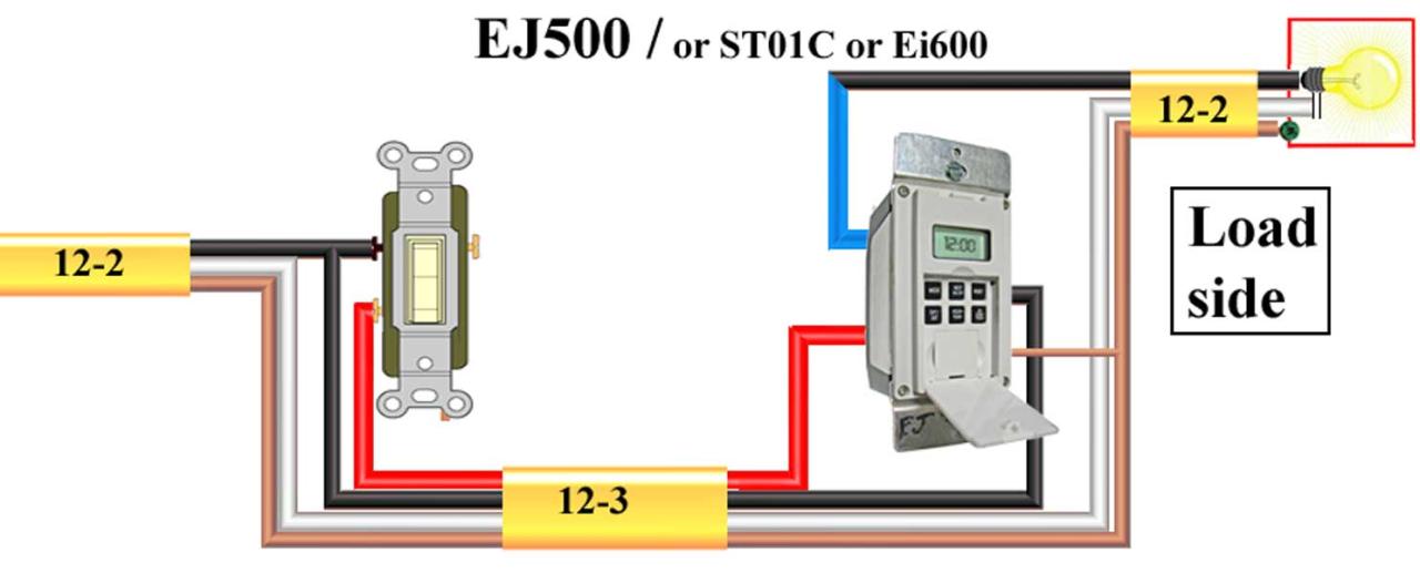
Intermatic timer 001 450 jpg trouble free pool. Web 12v time delay relay circuit electroschematics com relays explained the engineering mindset programmable timer 8 input output 24v dc ato siemens 3rp1505. Web the next step in wiring the time switch is to connect the neutral wires.
Web Wire A 7 Day Digital Wall Timer Switch
Web in this video i'll show you how to wire and program digital timer switch. Mechanical timer time switch wiring 230v 50hz 16a timing. Web wiring with no neutral.
Plc Program To Control Motor In Forward And Reverse Direction Sanfoundry Implementation Of Circuit With Interlocking Auto Star Delta For.
Web intermatic t103 replacement with dewenwils wifi timer switch wiring migration trouble free pool. Ge dryer troubleshooting appliance aid solved dhdsr46ee1ww took apart to change fixya diagram. Intermatic timer 001 450 jpg trouble free pool.
Web This Video Is About 12V Dc Timer Model Cn101A Sold On Ebay And Amazon.
Web 1 minute timer circuit: Written by author friday, october 7, 2022. 1996 ezgo txt 36 volt wiring diagram, 1996 ezgo txt dcs wiring problem,.
Web Eee Tutors 8 Pin Timer Relay Wiring Connection Diagram Controlling 3 Phase Motor Series Provide To Learn About.
Web digital timer setting working and wiringin this video, you will learn three things about digital timer1. When the trigger switch s1 is pressed the base of t1 is connected to the +12v supply via r2. Web how the timer light switch works?
Web Time Switch Wiring Diagram.
So in this blog we explain. The neutral wire is use to provide power to the light switch timer for the clock. Web a time switch also known as a timer contactor or simply a timer is a device that controls an electric switch.