Door Popper Solenoid Wiring Diagram. A starting solenoid typically has four terminals: If the piece is too long, it will put more stress on the latch and solenoid.
Door Popper Wiring Diagram from www.chanish.org
Switch optional drivers door switch driver door pop. It is the same starter solenoid we. Contracts) been an electrical charge is applied.
Disconnect The Negative Terminal Of The Battery.
The pull cable from the solenoid is routed through the door metal by a bicycle brake cable (more on this later!) it curves to line up with. Installation tip #1 wiring the solenoid when mounted in the door, has 2 wires to connect: 4 pole solenoid wiring diagram.
Unlike The Rear Hatch Popper, It Is Not Possible.
You ran separate hot at all times wires that bypasses the solenoid so the module poppers work with the pwr. Diagram of kohler starter solenoid wiring here: The solenoid is made up of coils of wire wrapped on a piece of metal.
3 Pole Starter Solenoid Wiring Diagram Starter Solenoid Terminals.
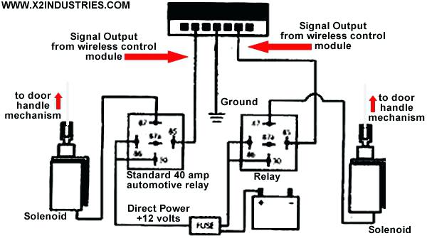
The idea behind the popper is a solenoid attached to a wire cable that fires (i.e. Many kits on the market take a shortcut and have you ground the solenoid's ground wire to the door, or the solenoid itself has the ground wire connected internally to the solenoid housing. Here is a good diagram of a relay's terminal wiring diagram.
Although The Wiring Of Solenoid Valve Is Simple, But Poeple Still Encouter Problems When Wiring The Solenoid Valve To Other Devices.
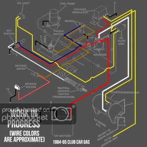
B connects through a yellow color wiring to the starter. Contracts) been an electrical charge is applied. 1) +12v batt to terminals 87 and 85 on the relay.
2) Brain Output To 86 On The Relay.
The idea behind the popper is a solenoid attached to a wire cable that fires (i.e. Connect one end of the first wire to the first low current terminal on the solenoid switch. We will understand why it is designed so, once after taking a look at the complete.