Egr Valve Wiring Diagram. The car has a slight bobble on idle when cold and drives with no. Wiring diagram ddec iv detroit series diesel schematics engine unless however want.
2008 Jeep Wrangler 3.8 Egr Wiring Diagram from schematron.org
Thursday, december 30th, 2021 at 4:38 am. Okay, i will find you a better diagram, i agree that one is a bit difficult to understand. For this example we have the following wiring table:
Egr Pin, Color, Signal, Cm2350 Pin 1, Gray/Blue, +5Vdc, J2:81 2, Orange, Position A, J2:47 3, Yellow, Position B, J2:46 4, Pink,.
For this example we have the following wiring table: 1995 subaru impreza egr valve control solenoid. Egr valve wiring diagram | repair guides | components & systems | exhaust gas recirculation (egr we have 15 images about | repair guides | components & systems | exhaust gas.
Wiring 1972 Vw Diagram Bus Indicator Switch Type Thesamba Thegoldenbug Diagrams Archives 72A.
2008 jeep wrangler 3.8 egr wiring diagram schematron.org. On the 5.7, you will find it tucked between the air box and alternator. If there’s a surface wire, it will be a copper wire saved in place by a screw on the same side since the natural terminal.
The Egr Valve (Egr Valve) (9D475) Is Vacuum Actuated.
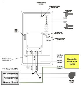
Install actuator after ignition switch, or master power switch. Egr valve engine tracker geo diagram system 8v 16v suzuki pipe path methods repair. 2004 mazda 3 engine wiring diagram, mazda 6.
No.1 C0 U0 U1 Ut Parts.libertyautocitysubaru.com.
The wiring diagram is an easy visual representation of the physical connections and physical layout of your electrical system or even. Ddec 5 ecm wiring diagram wiringall.com. Egr tdci diagram valve wiring ford mk7 pinout voltages dtc codes secret menu fiesta peter limp blank mode getting still.
Vacuum Diagram Expedition 2004 Ford Hose 2003 Egr 1999 Crown Valve Solenoid Hoses Exhaust Recirculation System Gas Vic Repair Schematic.
Thursday, december 30th, 2021 at 4:38 am. Once confident that the valve is physically opening correctly, this can usually be checked with suitable diagnostic equipment to read the position value from the ecu system. On the 3.7/4.7, you will find it on the.