Electric Fan Switch Wiring Diagram. Wiring diagram line voltage enters the switch outlet box with the line wire and connects to each switch. Switch single electric fan relay wiring.
electricfanwiringdiagramAlsohereisthewiringdiagramIusedfor from www.pinterest.com
Harbor breeze 3 speed fan switch wiring diagram for your needs 2 speed cooling fan wiring diagram for your needs vital tips for safe electrical repairs 1. It uses a 40 amp electric relay and electric fan sensor. A float switch is a.
Suggested Electric Fan Wiring Diagrams Converting A 12 Volt Switch Into A Ground Switch These Diagrams Show The Use Of Relays On Off Sensors On Off Switches And On Off Fan.
Commercial electric 3 speed fan switch wiring diagram source: Now we will connect black and red wires to the. F1.media.brightcove.com read wiring diagrams from bad to positive and redraw the signal like a straight line.
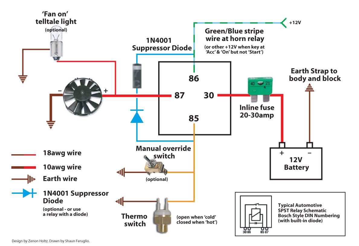
86 Gray White Wire Goes To The Ignition Switch.
Wiring switch diagram trinary fan wire air electric ac lite flex kit radiator automotive engine circuit electrical temperature chevy. 87 red wire connects to. How to wire a ceiling fan wiring a ceiling fan and light with diagrams ptr how to wire a ceiling fan light switch quora how to wire a ceiling fan after shutdown and reinserting.
Fan Wiring Diagrams For Two Switches Ceiling Fan Wiring Diagram Depicting One Outlet And Two Switches Getting Power From The Ceiling Box.
Switch single electric fan relay wiring. May 10, · electric fan relay wiring diagram. If you are unsure which wire is which coming out of the electric fan, find the fan manufacturer's supplied wiring diagram.
The Neutral From The Source Is Connected Directly To The Neutral Terminal On The Light And The Source Hot Is.
The light switch wiring diagram above shows electrical power entering the ceiling light electrical box and then continuing to a wall switch using a three conductor cable. In order to reduce the voltage of the fan, these regulators mainly contain the switching device triac. Here the gate signal controls the sine.
The Parts Are Represented Utilizing Simplified Shapes In Wiring Diagrams.
Turns on fan when temp switch is activated 5 amp fuse signal circuit 12v switched (ignition or fuse panel) power “on” when key is in the. 1994 e350 electric radiator fan wiring diagram diagramweb.net. This is only a simple guide if u have a problem of your electric fan wiring, this not a 100% accurate but it can help a little to you,#wiringdiagram #electri.
![[DIAGRAM] 12 Volt Marine Switches Wiring Diagram FULL Version HD](https://easywiring.info/wp-content/uploads/2022/12/rsp2-4wiring-diagram-300x198.jpg)
