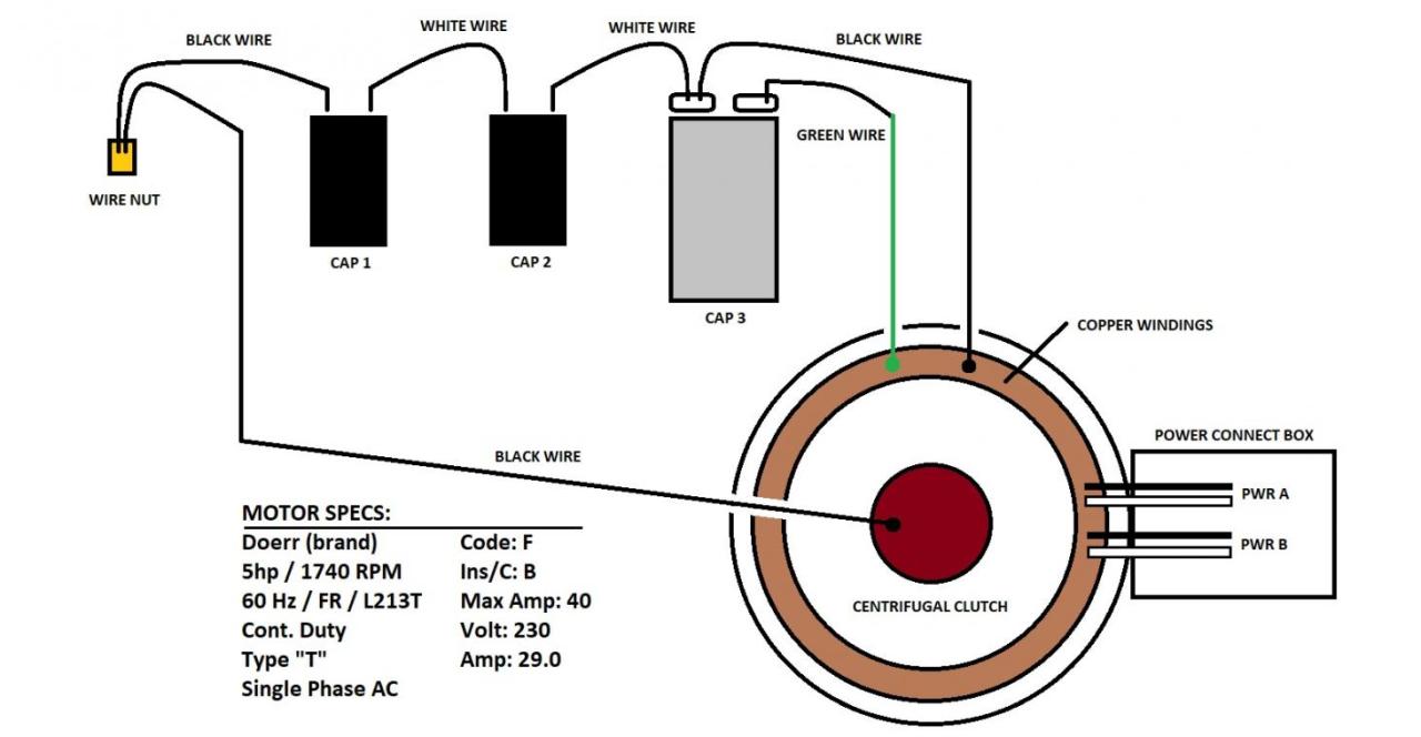
Electric Motor Capacitor Wiring Diagram. Just as its name implies, this single phase motor diagram will work with a split phase generated by a capacitor. Electric motor start run capacitor operation install air conditioning compressor other boost or capacitors 4 wire cooler motor wiring diagram and connection procedure etechnog.
5 HP Motor/ Capacitor question from www.practicalmachinist.com
China cbb61 10uf ceiling fan wiring diagram ul capacitor. Push the wire terminal on the start capacitor relay's 'common' wire,. Insides of emerson motor (not confirmed) see plan only (on page 1) on.
Motor Starting Capacitor Wiring Diagram.
Black= power lead, it will go where your old black wire went, should be a power contact. The only thing missing from this graphic is the. Single phase motor wiring diagram and examples wira electrical on a 115 230v need to know what exactly is connected the purple wire l1 or incoming s n actually i.
How To Replace A Condenser Fan.
Just as its name implies, this single phase motor diagram will work with a split phase generated by a capacitor. A wiring diagram usually gives guidance very nearly the relative outlook and bargain of devices and. China cbb61 10uf ceiling fan wiring diagram ul capacitor.
What Are Dc Motors ?.
Permanent split phase capacitor motor wiring diagram. Insides of emerson motor (not confirmed) see plan only (on page 1) on. Wiring a capacitor to start a motor begins with the connection of the positive terminal of the motor to the resistor.
Start Capacitors Are Wired Into The Auxiliary Winding Circuit Of The Motor And Are Disconnected From The Main Winding Circuit By The Centrifugal Switch Once The Motor Has Reached A.
Push the wire terminal on the start capacitor relay's 'common' wire,. 17 images about [cd_2362] copeland compressor start capacitor diagram download diagram : Our most sage advice is not necessarily only look in the diagram, but.
A Star Delta Is Used For A Cage Motor Designed To Run Normally On The Delta Connected Stator Winding.
Dc motors are electric motors that are powered. Single phase terminal markings identified by color: Split phase permanently connected capacitor electric motor wiring diagram.