Electronic Throttle Body Wiring Diagram. Web the purpose of the gm throttle body wiring diagram is to provide a complete visual representation of the circuitry within the throttle body and its associated. Web january 08, 2023 by electronic throttle body.
P0122 Code Throttle Position Sensor/Switch A Circuit Low Input In from www.carparts.com
With the advent of torque based engine management systems, the precise control and robust performance of the throttle body. Web a gm throttle body wiring diagram is a visual representation of the electrical connections and components in the gm throttle body system. (i) an accelerator pedal module (ideally with two or more independent sensors), (ii) a throttle valve that can be opened.
Pin 16 On The Ecu +5V Throttle.
Web the purpose of the gm throttle body wiring diagram is to provide a complete visual representation of the circuitry within the throttle body and its associated. Web january 08, 2023 by electronic throttle body. In this hev conversion project, to reduce the additional required.
Web A Typical Etc System Consists Of Three Major Components:
Web electronic throttle body wiring diagrams provide essential information to automotive mechanics and technicians who work with modern gasoline engines. With the advent of torque based engine management systems, the precise control and robust performance of the throttle body. Web the electronic throttle body wiring diagram is a complex map of the connections between the various components of the engine and its associated sensors.
Web A Gm Throttle Body Wiring Diagram Is A Visual Representation Of The Electrical Connections And Components In The Gm Throttle Body System.
Larger photo in a gasoline engine, the engine speed is controlled by the amount of air that enters the engine. Web model based design of electronic throttle control. (i) an accelerator pedal module (ideally with two or more independent sensors), (ii) a throttle valve that can be opened.
Web Filthy Rich Shows You How To Save Money By Replacing A Throttle Plug Wire Instead Of The Whole Throttle Body Assembly.follow Rich On Twitter.
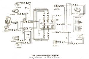
Pierce the wire with the probe as far away as possible from the pcm connector. Pin 29 on the ecu sub circuit throttle body ecu +5v: Web the wiring diagram is available in the service manual.
The Details Of The Sensor And How The Motors Work I Don't Think Anyone Here Knows.