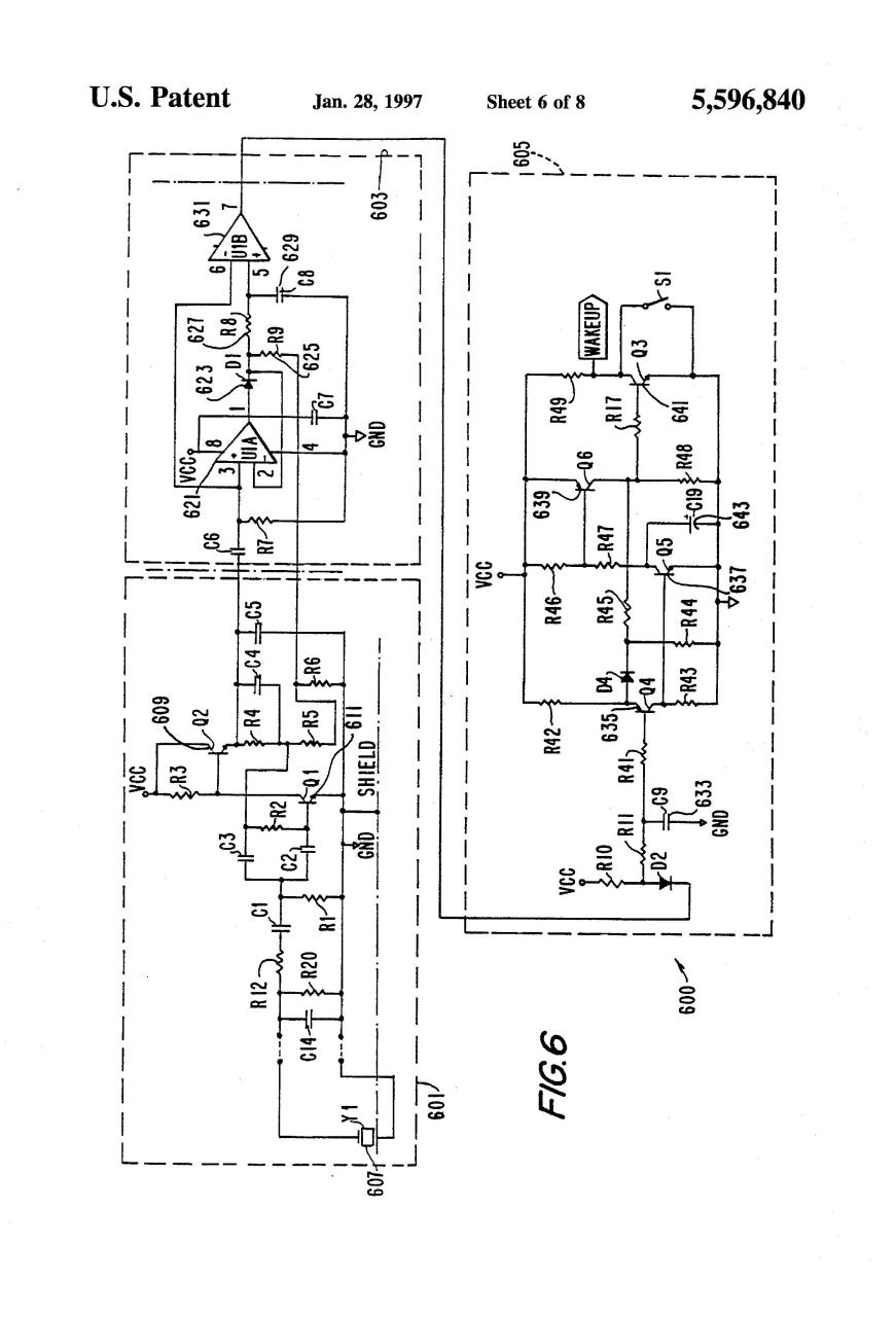
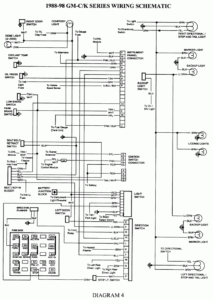
Genie garage opener wiring diagram data entrancing door sensor. It shows the parts of the circuit as streamlined shapes and the power as well as signal connections in between the tools.

New Wiring Diagram Garage Door Opener Sensors Diagram Diagramsample Diagramtemplate Wiringdiagram Diagramchart Wo Garage Doors Garage Door Sensor Diagram
Garage door openers include a photo electric sensor system to help prevent damage to the door or opener.

Genie garage door sensor wiring diagram. Wiring a sensor for a genie garage door opener is much like any other opener. General troubleshooting genie excelerator garage door opener. It reveals the elements of the circuit as streamlined shapes and the power as well as signal connections in between the devices.
The sensor emits an infrared beam that when broken causes the opener to stop closing the door and reverses the movement back to the open position. Genie garage door opener wiring diagram genie garage door sensor wiring diagram for opener with 1024 0. Variety of genie garage door opener sensor wiring diagram.
Variety of genie garage door sensor wiring diagram. Craftsman garage door opener wiring diagram collection. Genie garage door opener wiring schematic collections of genie garage door opener wiring diagram in 9 natebird me beauteous.
A wiring diagram is a streamlined standard photographic representation of an electric circuit. Electrical wiring diagram for garage new genie garage door opener. Wiring a sensor for a genie garage door opener is much like any other opener.
Place the two limit switches on the garage door opener s rail so that the arrows are facing away from the. A wiring diagram is a streamlined standard pictorial depiction of an electrical circuit. Variety of genie garage door opener sensor wiring diagram.
It reveals the elements of the circuit as streamlined shapes as well as the power and also signal connections in between the tools. Genie excelerator manual online. Variety of genie garage door safety sensor wiring diagram.
A wiring diagram is a simplified conventional photographic representation of an electric circuit. A wiring diagram is a streamlined traditional pictorial representation of an electric circuit.

Detached Garage Wiring Diagram Door Genie Sensor Opener How To Wire Within Mccb Eletricista

Unique Wiring Diagram Garage Door Sensor Diagram Diagramsample Diagramtemplate Wiringdiagram Diagramcha Garage Door Sensor Garage Doors Garage Door Opener

Unique Wiring Diagram Garage Door Diagram Diagramsample Diagramtemplate Wiringdiagram Diagramchart Garage Doors Electric Garage Doors Garage Door Opener

Best Wiring Diagram For Genie Garage Door Opener Sensor Doors Design In 2020 Liftmaster Garage Door Liftmaster Garage Door Opener Garage Door Opener Remote

New Wiring Diagram Electric Garage Door Diagram Diagramsample Diagramtemplate Wiringdiagram Diagramchart Worksheet Wo Garage Doors Diagram Diagram Chart

New Wiring Diagram For Automatic Gate Label Templates Low Voltage Outdoor Lighting Garage Door Sensor

New Chrysler Electric Fan Wiring Diagram Craftsman Garage Door Craftsman Garage Door Opener Garage Plans

Marine Radio Wiring Diagram Wiringdiagram Org Marine Radios Diagram Diagram Design

Kenwood Kdc 355u Wiring Diagram Diagram Harley Davidson Harley

Unique Wiring Diagram Garage Door Diagram Diagramsample Diagramtemplate Garage Doors Garage Door Opener Troubleshooting Electric Garage Doors

16 Motorcycle Horn Relay Diagram Motorcycle Diagram Wiringg Net In 2020 Ceiling Fan Wiring Ceiling Fan Switch Light Switch Wiring

Unique Wiring Diagram For A Garage Consumer Unit Diagram Diagramtemplate Diagramsample Electronica

The Best 24 Smart Home Wiring Diagram Https Bacamajalah Com The Best 24 Smart Home Wiring Diagram With Images Electrical Wiring Diagram Door Repair Baseboard Heater

Unique Wiring Diagram Garage Door Diagram Diagramsample Diagramtemplate Garage Doors Doors Garage Door Remote

Best Of Wiring Diagram For Shop Lights Diagrams Digramssample Diagramimages Wiringdiagra Garage Door Safety Garage Door Sensor Automatic Garage Door Opener

Unique Wiring Diagram For Domestic Consumer Unit

Genie Garage Door Sensor Wiring Diagram Britishpanto And Opener In 2020 Garage Door Sensor Liftmaster Garage Door Garage Door Opener

New Wiring Diagram Auto Electrical Electrical Wiring Diagram Trailer Wiring Diagram Electrical Diagram


