Sometimes wiring diagram may also refer to the architectural wiring program. You are able to find this guidebook easy to make use of and also extremely cost effective.
What Is 3 Phase Electric In 2020 Electrical Engineering Books Power Engineering Electrical Wiring
240v for the heating element and 120v for the controls and drum motor.

10 30r wiring diagram. Nema 10 30r 240 volt 30 amp plug wire diagrams wiring diagram 30 amp plug wiring diagram. We hope you enjoyed it and if you want to download the pictures in high quality simply right click the image and choose save as. The simplest approach to read a home wiring diagram is to begin at the source or the major power supply.
Leviton nema 10 30r wiring diagram wiring diagram is a simplified welcome pictorial representation of an electrical circuit. Nema 10 30r wiring free download diagram schematic. Nema 10 30r 3 pole 3 wire non grounding rated 30a 120 240v no ground typically used for older dryers that do not have a ground leg and that require dual voltage.
Frequently confused with the. It shows the components of the circuit as simplified shapes and the capacity and signal links surrounded by the devices. The wiring diagram on the opposite hand is particularly beneficial to an outside electrician.
Shop 3 pole 3 wire 30a 125 250v non grounding receptacle 10 30r by hubbell wiring device kellems hbl9350 at graybar your trusted resource for straight blade receptacles and other hubbell wiring device kellems products. Wiring diagrams are made to be easy to comprehend and easy to create. Here we have another image control 240 volt with wemo 240 volt plug wiring diagram featured under nema 10 30r 240 volt 30 amp plug wire diagrams wiring diagram 240 volt plug wiring diagram.

Build A 240v Power Adapter For Your Mig Welder Make Home Electrical Wiring Electrical Wiring Electrical Installation

50 Amp Rv Plug Wiring Diagram 2 Electrical Plug Wiring Outlet Wiring Power Plug

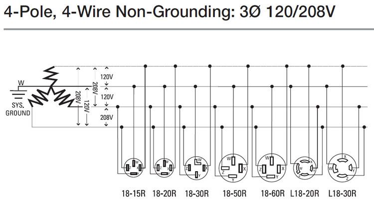
Nema Chart Gif 606 640 Electricity Basic Electrical Wiring Plugs

Rv Receptacle Wiring Diagram Pdf Download Outlet Wiring Trailer Wiring Diagram Diagram Design

How To Wire 240 Volt Outlets And Plugs Home Electrical Wiring Electrical Wiring Electrical Wiring Diagram

American 3 Pole 250v 30a Nema 10 30r Us Generator Outlet Anti Off Industrial Power Socket Plug Inline Wire Conne 10 Things Wire Connectors Electrical Equipment

Wiring Diagram Outlets Beautiful Wiring Diagram Outlets Splendid Line Wiring Diagram Hel Electrical Circuit Diagram Electrical Wiring Diagram Pool Electrical

220 3 Phase Wiring Diagram In 2020 Wire Electrical Wiring Home Electrical Wiring

How To Wire 240 Volt Outlets And Plugs Electrical Wiring Diagram Electrical Wiring Wire

How To Wire A 30 Amp Rv Plug Electric Problems In 2020 Rv Electricity Plugs

Ac Works S1030pr 30a 250v Nema 10 30 3 Prong Dryer Heavy Duty Stw 10 3 Extension Cord Extension Cord Dryer Outlet Extensions

How To Wire 120 And 240 Volt Outlet And Plug Wire Electrical Wiring Home Electrical Wiring

Ac Works S1030pr 30a 125 250v Nema 10 30 3 Prong Dryer Heavy Duty Stw 10 3 Extension Cord Extension Cord Thick Extensions Outdoor Extension Cord

Wiring Diagram For 220 Volt Dryer Outlet Bookingritzcarlton Info Dryer Outlet Wire Diagram

New Mercedes Glow Plug Relay Wiring Diagram Dryer Plug Dryer Outlet Wire

Putting A 15 Amp Receptacle On A 20 Amp Breaker Firehouse Com Receptacles Breakers Configuration
Pin On Ac Works Products

Ac Works Ad14501030 14 50p 50a 4 Prong Plug To 10 30r 3 Prong Dryer Outlet In 2020 Dryer Outlet Plugs It Works

Understanding 240v Ac Power For Heavy Duty Power Tools Make Electrical Plug Wiring Electrical Wiring Outlets Free Energy Generator