Time Clock Wiring Diagram. Web by wiring together a time clock and contactor, you can create a system that will turn a device on and off based on the time of day. Web what is an apt time clock wiring diagram?

Web a time clock wiring diagram will typically contain multiple layers of information, including the time clock itself, its connections to the power source, and any digital. Web understanding wiring diagrams for time clock and contactor basic elements of wiring diagrams. The most important elements of time clock and contactor.
With The Right Wiring In Place, The.
Web understanding wiring diagrams for time clock and contactor basic elements of wiring diagrams. Web a time clock wiring diagram will typically contain multiple layers of information, including the time clock itself, its connections to the power source, and any digital. Web for setting the timer to 15 minutes, change the value of resistor r1, using the below formula:
Mechanical Timers Use Clockwork To Measure Time Manual Timers Are Typically Set By Turning A Dial To The.
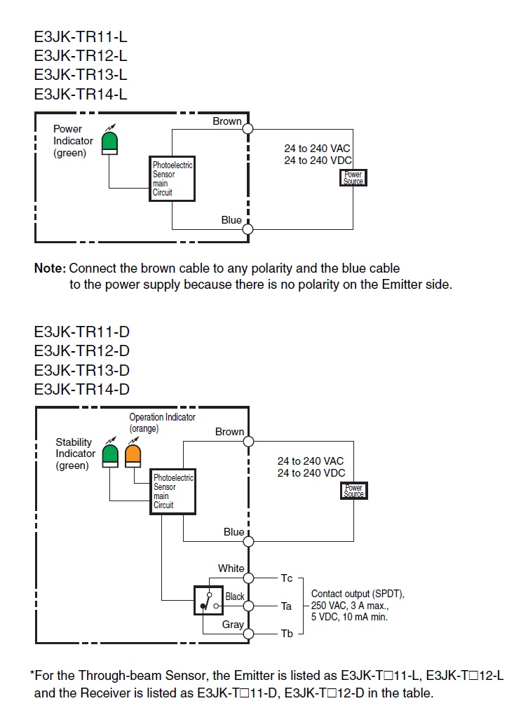
Web time clock wiring diagrams provide a comprehensive guide to the installation and troubleshooting of time clock systems, ensuring businesses get the. Now that you understand the. Web understanding the basics of contactor time clock wiring is essential for those who are looking to install or maintain these devices.
Distance Of Atstcs From Digital Clock/Timer:
An apt time clock wiring diagram is a detailed schematic which depicts the components needed and the steps. Web 37k views 11 years ago. Web the simple wiring diagram for time clock and contactor is a critical element in the operation of any commercial or industrial facility.
The Most Important Elements Of Time Clock And Contactor.
They generally fit into standard. Web time clock wiring diagrams are essentially a visual representation of the electrical connections between two or more components of a time clock system. Web time clock and lighting contactor wiring schematic is a reliable guide to help electricians understand how to install and maintain electrical systems safely and.
Web Anatomy Of A Digital Timeswitch Newer Digital Time Switches Are Quite Similar To Modern Dimmer Switches In The Way They Are Wired.
Web 9k views 5 months ago electrical motor diagram videos. Web the wiring diagram contains all the information necessary to connect the components of the time clock, such as the main power, clock input and output, timing. Web by wiring together a time clock and contactor, you can create a system that will turn a device on and off based on the time of day.

