For hvac technicians and others who need to determine wire color code conventions connections for both new and older heating and cooling equipment heat pumps split systems etc here we give themost common conventions for identifying or connecting thermostat wires based on wire color and wiring terminal identification letter s. It shows the elements of the circuit as streamlined forms and the power and signal links between the devices.
New Basic Wiring Colors Diagram Wiringdiagram Diagramming Diagramm Visuals Visualisation Ac Wiring Electrical Circuit Diagram Electrical Wiring Diagram
In either case it is crucial to find the wiring diagram for the unit.

Hvac wiring diagram colors. Basic thermostat wiring colors air conditioner systems always remember when changing a thermostat for a new thermostat to take a photo of the colors and where they go on the old thermostat or get a pencil and paper and write it down. Collection of hvac wiring diagram. Thermostat wiring diagrams furnaces.
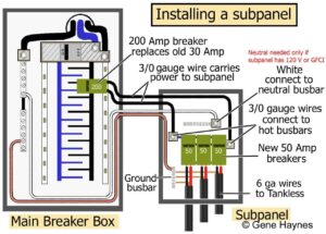
The incoming 240v power is split into two legs. Thermostat wiring colors and terminals. It is better to take a good up close photo of the old thermostat and what terminals the colored wiring are terminated.
The color of wire r is usually red and c is black. Heat pump thermostat wiring a typical wire color and terminal diagram. However an installer may have used any color when installing the wire to the w2 terminal.
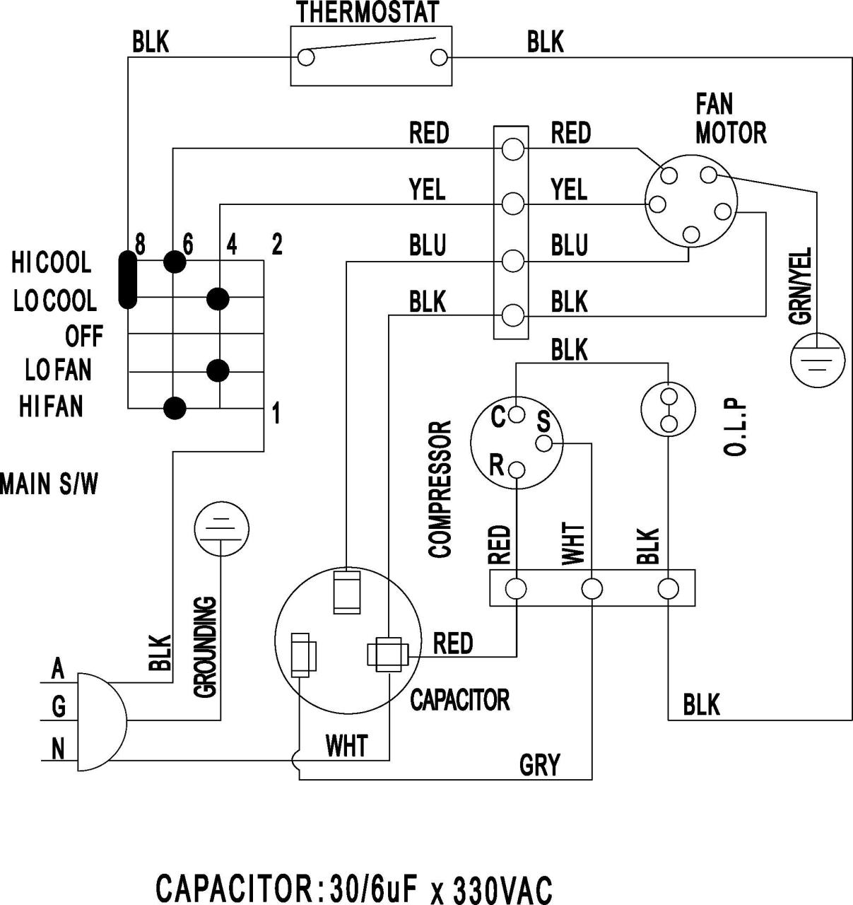
We will go over which speed each wire color is an. The red wire should always come from the hot side of the 24 volt transformer. A majority of the time the hvac wiring color is brown for this particular terminal.
Usually the electrical wiring diagram of any hvac equipment can be acquired from the manufacturer of this equipment who provides the electrical wiring diagram in the user s manual see fig 1 or sometimes on the equipment itself see fig 2. A wiring diagram is a streamlined traditional photographic representation of an electrical circuit. Each leg can provide 120v hot to neutral and the two legs together will supply 240v which is used to supply heavy loads such as air conditioning compressors and cookstoves.
A cooling system with two compressors or a two stage compressor need a y2 terminal so the thermostat is able to control the second stage of cooling. Homes in north america are supplied with a 120 240v single phase electrical service. As shown in the diagram you will need to power up the thermostat and the 24v ac power is connected to the r and c terminals.
Therefore you will use the following color code for simple thermostat wiring. These two connections will ensure that there is power to the thermostat that you are operating. C is known as the common terminal.
Finally this way you can match up the appropriate wire color coming from the thermostat to what it controls in the equipment. Terminal r or terminal rh for the red wire. 2 how to get the electrical wiring for air conditioning systems.
Heating only thermostat wiring diagrams if you only have a furnace such as a gas furnace oil furnace electric furnace or a boiler.

Thermostat Wire Color Code Thermostat Wiring Honeywell Thermostats House Wiring

Heat Pump Thermostat Wire Colors Hvac Thermostat Thermostat Wiring Honeywell Thermostats

Electrical Wiring Diagrams For Air Conditioning Systems Part Two Electrical Kn Electrical Wiring Diagram Air Conditioning System Electrical Circuit Diagram

Electrical Wiring Diagrams For Air Conditioning Systems Part Two Electrical Knowhow Electrical Diagram Air Conditioning System Electrical Wiring Diagram

Single Stage Heat Pump Thermostat Wiring Diagram Thermostat Wiring Hvac Thermostat Thermostat Installation

Carrier Thermostat Wiring Diagram With Image Of Furnace Brilliant

Guide To Color Coding For International Wiring International Electrical Wiring Electrici Electrical Wiring Colours Electrical Wiring Home Electrical Wiring

Wire A Thermostat Thermostat Wiring House Wiring Home Electrical Wiring

Basic Hvac Wiring Diagrams Schematics At Diagram Pdf Diagram Diagram Design Hvac

Wiring Diagram For Ac Unit Elegant Goodman Condenser Wiring Electrical Circuit Diagram Electrical Wiring Diagram Ac Wiring

Electrical Wiring Diagrams For Air Conditioning Systems Part One Electrical Knowhow Electrical Diagram Air Conditioning System Electrical Wiring Diagram

Air Conditioner Control Thermostat Wiring Diagram Hvac Systems Thermostat Wiring Air Conditioner Refrigeration And Air Conditioning

Thermostat Wiring Colors Code Hvac Control Thermostat Wiring Hvac Tools Thermostat

New Basic Wiring Colors Diagram Wiringdiagram Diagramming Diagramm Visuals Visualisation Electrical Wiring Diagram Electrical Circuit Diagram Ac Wiring

Bryant Heat Pump Thermostat Wiring Diagram On Hvac Capacitor Wiring Diagram Thermostat Wiring Heat Pump System Heat Pump
Carrier Hvac Thermostat Wiring Diagram Hvac Thermostat Thermostat Wiring Carrier Hvac

Thermostat Wiring Colors To Labels Thermostat Wiring Hvac Thermostat Heating Thermostat

Cool Intertherm Thermostat Wiring Schematic Photos Thermostat Wiring Trane Heat Pump Heat Pump

Infographic On Dc Power Circuit Wiring Color Codes Infographic Electrical Engineering Electrical Wiring Colours Color Coding Label Templates