Lennox Thermostat Wiring Diagram. Installation instructions page 20 of lennox international inc air conditioner 06 11 50672801 user guide manualsonline com hs29 311 not turning on diy home improvement. Thermostat wires through wall level figure 1.
Famous Lennox Thermostat Wiring Diagram Image Collection Best At from www.pinterest.com
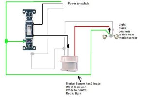
I explain what each of the letter t. Red, white, blue and green? This picture ( wire a thermostat for lennox furnace thermostat wiring diagram) above is actually classed along with:
He Can Make The Repairs Himself, But We Need A Read More Switching From A.
Lennox furnace thermostat wiring diagram from www.askmehelpdesk.com effectively read a wiring diagram, one offers to know how typically the components in the program operate. Lennox furnaces, like other products, have wiring diagrams for their equipment. Thermostat wires through wall level figure 1.
G21/Gsr21 Pwm (Pulse Width Modulation) Signal Or Fixed 24 Vac Or Tion And Service To.
This picture ( wire a thermostat for lennox furnace thermostat wiring diagram) above is actually classed along with: I have tried the following and this comes back as a. Furnace wiring lennox diagram gas wire thermostat heat nest.
Prodigy 2.0 (M3 Unit Controller) Bacnet.
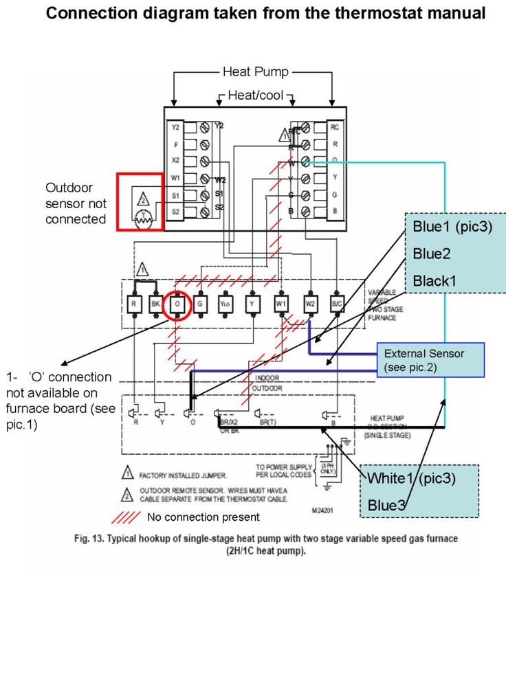
Connect the outdoor sensor (if used) to the t connections on the thermostat. Red, white, blue and green? In this hvac installation training video, i show how to wire the low voltage thermostat wires into a furnace and ac unit.
I Explain What Each Of The Letter T.
The thermostat uses one wire to control the primary functions of your hvac system, such as heating, cooling, and fan. Thermostat wiring diagrams (color code guide) when you buy a new thermostat wiring bundle, it will come with a slashed number. We’ve made it easy for you to find the resources you need, including product brochures and owner's.
You Will Typically Find 18/5, 18/6,.
See the diagram below for the role of each wire in. Simple and efficient temperature control. Conventional heat/cool and heat pump.