Same as all the diagrams everywhere don t need add any of the resistors or other components from these diagrams. Wire a switched outlet.
Http Www Hobbycncaustralia Com Au Instructions Ii75wirelimitswitch Htm Diy Cnc Router Cnc Controller Arduino Cnc
The control wire connects to the electrical device that the limit switch is intended to control.

Limit switch wiring diagram. Most limit switches contain the following functional parts in one form or another. Step by step instructions on how to wire a switched outlet. Sometimes it is handy to have an outlet controlled by a switch.
A wiring diagram is a streamlined conventional photographic depiction of an electric circuit. Limit contacts are suitable for line voltage low voltage or millivoltage circuits. Jan 24 18 02 09 pm.
2018 10 01 john ford said. Jan 24 18 02 26 pm. Is it ok to wire the limit switch backwards with wires reversed in polarity from the instructions.
Limit switch open or close es11. Variety of honeywell limit switch wiring diagram. Load voltage to the fan is wired at the upper left push in terminal.
The push button is actuated by hand whereas the limit switch is operated mechanically. Step 4 insert the exposed conductor of the control wire into the no or the nc terminal and secure it by tightening the terminal retention screw with a screwdriver. Line voltage is wired at the bottom left push in terminal.
The l4064b has a manual switch to provide continuous fan operation mounting adapters for replacing competitive devices adapters for wiring convenience and a strain relief bushing for protecting the wiring from damage due to field abuse. In some limit switches the actuator is attached to an operating head which translates a rotary. The actuator is the part of the switch which physically comes in contact with the target.
Want to turn a lamp on with a light switch. Wiring diagram 1 phase 3 wire motor gearbox rsu limit switch notes. The main function of the limit switch is to open or close an electric circuit when the physical limit of the operation of the controlled device has reached.
Warning on wiring limit controls and switches in reverse polarity question. Switched outlet wiring diagram. It reveals the components of the circuit as streamlined shapes and the power and also signal links in between the devices.
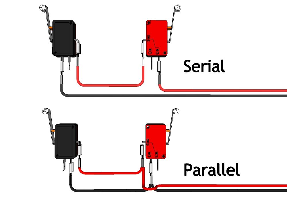
Honeywell fan limit switch wiring diagram architectural circuitry representations reveal the approximate areas and affiliations of receptacles lights as well as long term electric solutions in a building. Then as usual your limit switch wires one wire from each switch to ground and the other to one of the pins 9 10 or 11 grbl v 08. Limit switch working principle the limit switch is like a 1 no 1 nc push button.
To reverse direction of rotation of the rw motor swap connections v1 and w1 on the electrical motor connection strip. To reverse the limit switches of the rsu limit switch system swap the wiring of terminal 1 and 7 at the rsu limit switch unit.

Dc Motor Reversing Circuit Limit Switch Elektronnaya Shema
Forward Reverse Motor Control Wiring With Limit Switches Youtube Electrical Diagram Switches Electrical Wiring Diagram

Motor Limit Switch Circuit Circuit Switch It Works

Three Phase Dol Starter Control And Power Wiring Diagram Reverse Forward With Limit Switch Youtube Light Switch Wiring Electrical Jobs Cable Tray

External Limit Switch Kit For Actuators Linear Actuator Actuator Switches

Pin On Inspiring Ideas

Dc Motor Reversing Circuit Limit Switch Circuit Motor Switch

Wiring A 230v Air Compressor In 2020 Diagram Electrical Circuit Diagram Diagram Design

Example Of How To Use A Micro Switch Electronic Circuit Design Switch Words Micro

3 Phase Motor Reverse Forward Limit Switches Control Diagram In English Youtube Reverse Switches Telephone Cables

How To Set Up Limit Switches With A Wired Dpdt Switch For Reverse Forward Controls Switch Switches Circuit Design

Pin Di Letter Alimy For Us

Adding A Limit Switch Plc Programming Ladder Logic Electronic Engineering

2 Limit Switches Wiring Using Same Pin Arduino Arduino Arduino Programming Arduino Projects

Wiring Diagram Electrical Wiring Diagram Electrical Electrical Wiring Diagram Carrier Furnace Electric Furnace

How To Set Up Limit Switches With Diodes And Dpdt Or Wireless Remote Reverse Forward Switch Switches Circuit Design Variable Speed Motor

External Limit Switch Kit For Actuators In 2020 Linear Actuator Actuator Switch

Wire Limit Switches To Jk02 M Diy Cnc Router Diy Cnc Cnc Machine Projects

Trim Limit Switch And 110 Amp Fuse For Mercruiser Wiring Diagram Wiring Diagram Diagram Wire