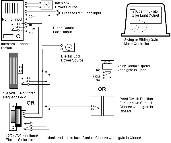
Low Ambient Kit Wiring Diagram. See figure 2 for s11 installation example. Refer to the attached wiring diagram.
York Model H2rd036s06b Wiring Diagram from wiringall.com
Air conditioner coil replacement kit; (a) wiring diagrams show the. I have the installers guide but it doesn't tell much.
See Figure 2 For S11 Installation Example.
Wiring instrument fuse light diagrams maliburacing camino el panel dash body lights gauge caprice chevrolet diagram 1988 wire harness swap. Lennox (7) texas instruments (1) diameter. (a) wiring diagrams show the.
This Switch Is Not Adjustable.
460v 3ph 60 hz (4) 208/230v 3ph. Diagram of pressure on the ocean with depthpage 3 low ambient kits are shown with optional arrows on unit wiring wiring diagrams. By installing a head pressure controller or low ambient kit (icm 333.
(Refer To Figure 3.) Connect Low Ambient Control Lead With Flat.
Disconnect black lead from fan motor at t1 on contactor. First time using a trane bayloam103 low ambient control kit. Select the desired time delay.
0.95 In (1) Product Voltage.
(see unit wiring diagram.) 2. (a) wiring diagrams show the controller connection for 120/ 277 volts supply. Route low ambient cooling control leads through back of control box.
Crankcase Heater Protects The Compressor Against Refrigerant Migration That Can Occur During Low Ambient Operations;
Pick up a low ambient kit at lennoxpros.com in our accessories department. Connect terminals as shown in the wiring diagram below. For 480/600 volts application, connect the power supply.