Msd 8 Plus Wiring Diagram. This will protect the ignition in the event of wrong connections. Web the msd ignition digital 6 plus wiring diagram allows you to easily identify the specific pins and wiring colors associated with the ignition system.
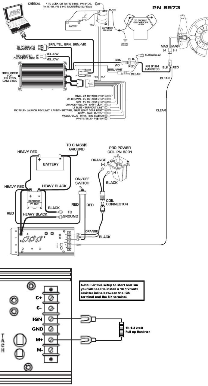
Web the coil should be mounted near the distributor cap to keep the length of the coil wire minimal. Do not use solid core spark plug wires with any msd component. If using a timing control, its yellow wire connects to m+.
This Book Is A Collection Of Component Installation Procedures,.
Never connect to the alternator. Web installation instructions 1 parts included: An msd cannot be used on vehicles with cd ignitions or distributorless ignition systems.
Do Not Use Solid Core Spark Plug Wires With Any Msd Component.
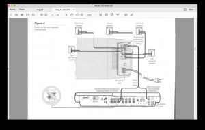
Web the coil should be mounted near the distributor cap to keep the length of the coil wire minimal. Figure 1 wiring the msd 8 with a crank trigger. Web this wire connects directly to the battery positive (+) terminal or to a positive battery junction or the positive side of the starter solenoid.
It Is Only Used When Adding Power Grid Modules.
Before drilling mounting holes, make sure the wiring harness reaches the coil. This will protect the ignition in the event of wrong connections. Web that is why we have assembled the msd ignition wiring diagrams and tech notes book.
You Can Set Three Different Rev Limits That Can Be Used During The.
Provides over 150 pages of diagrams and details on msd's ignition line Solid core spark plug wires cannot be used with an msd ignition control. Led indicator there is an.
Web Wiring Diagrams And Tech Notes.
Web digital operation the msd digital 6 plus uses a high speed risc microcontroller to control the ignition’s output while constantly analyzing the various inputs such as supply. To program the unit for other engines, remove the. If using a timing control, its yellow wire connects to m+.