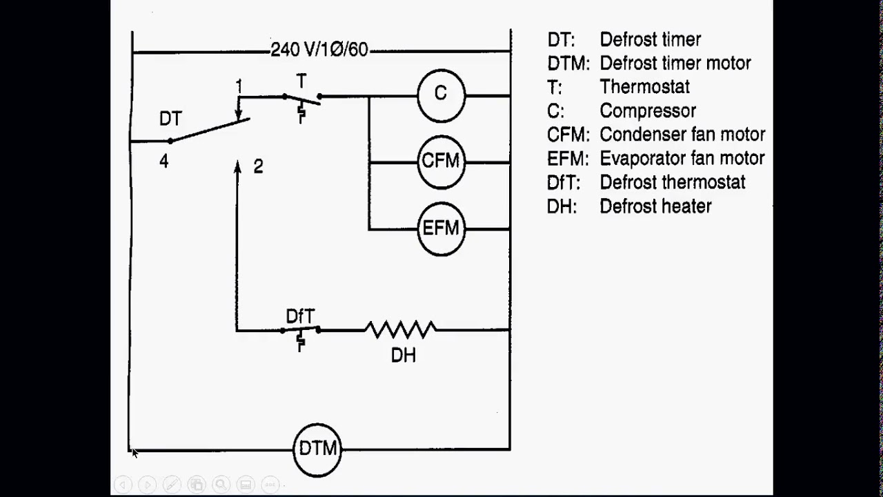
Ladder Diagram Vs Wiring Diagram. Web the name “ ladder diagram ” is derived from the program’s resemblance to a ladder with two vertical rails and a series of horizontal rungs between them. Web the ladder diagram consists of two vertical lines representing the power rails.
Ladder Diagrams YouTube from www.youtube.com
A wiring diagram is a simple visual representation of the physical connections and physical layout of an electrical system or circuit. Web wiring diagram vs schematic diagram. Web answer (1 of 2):
It Is Common To Mistake A Wiring Diagram For A Schematic Diagram Or Vice Versa.
The i / o connection of plc is the link between the main circuit and plc ladder diagram. Modern refrigeration and air conditioning 21st edition online textbook. Web how to construct wiring diagrams controls.
On The Left Line, There Is A Positive Voltage Supply.
A block diagram is a type of electrical drawing that represents the principle components of a complex system in the form of blocks interconnected by lines that. Web the ladder diagram consists of two vertical lines representing the power rails. It does not show the actual locations of the components.
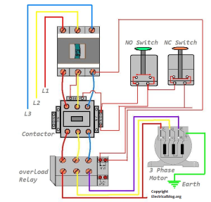
A Wiring Diagram Is A Simple Visual Representation Of The Physical Connections And Physical Layout Of An Electrical System Or Circuit.
Hanya saja simbol no atau nc. Web plc ladder logic examples lamp control using timers engineering arena four way traffic by technical hub based 4 light system instrumentationtools program. Web answer (1 of 2):
But, These Days The Terms Ladder Diagram, Ladder.
What is the difference between a circuit diagram, and a ladder diagram. Web none of the contacts or coils seen in a ladder diagram plc program are real; Check out our free hvac courses & certifications:
Web Understand Ladder Diagram Through I / O Wiring Diagram Of Plc.
The two vertical lines are called “rails” and attach to opposite poles of a. Web the name “ ladder diagram ” is derived from the program’s resemblance to a ladder with two vertical rails and a series of horizontal rungs between them. Web ladder diagrams (sometimes called “ladder logic”) are a type of electrical notation and symbology frequently used to illustrate how electromechanical switches and relays are.