Product connect a jumper between the h2 and h3 terminals and bring the v in on h1 h4. Otherwise the arrangement won t work as it should be.

Wiring Diagram For 220 Volt Single Phase Motor Http Bookingritzcarlton Diagrama De Instalacion Electrica Diagrama De Circuito Electrico Diagrama De Circuito
Each component ought to be placed and connected with other parts in particular way.

Single phase transformer wiring diagram. 240 volts delta secondary. Neutral x0 provided on three phase 4 wire primary volts delta transformers 15 kva through kva are equipped with a volt lighting tap. Single phase three phase wiring diagrams 1 phase 3 phase wring the star delta y δ 3 phase motor starting method by automatic star delta starter with.
240 volt single phase wiring diagram 220 volt single phase motor wiring diagram 220 volt single phase wiring diagram 240 volt single phase motor wiring diagram every electric arrangement is composed of various unique components. 2 5 bnfc x1 h1 x2 x3 h2 h3 x0 3 2 1 3 2 1 3 2 1 connectconnect primary primary inter secondary. 2 5 bnfc x1 h1 x2 x3 h2 h3 x0 3 2 1 3 2 1 3 2 1 connect connect primary primary inter secondary.
If the proper nominal voltage isn t available at the primary of the transformer primary taps may be needed to bring. It uses a single pole double throw type transfer switch to impress a high voltage across the capacitor during start up. Another split phase capacitor run type of electric motor utilizes a capacitor transformer unit and is of the split phase squirrel cage type with the main and auxiliary winding s physically displaced in the stator.
Single phase transformers connected in the closed or the open delta don t need to be the same kva rating. Single phase transformer primary and secondary wiring. Beautiful 480v to 240v single phase transformer wiring diagram what is a wiring diagram.
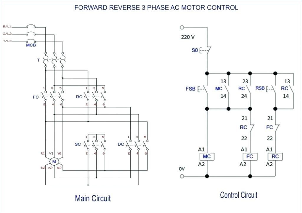
240 volts delta secondary. Wiring capacitors resistors semiconductors table 1 standard elementary diagram symbols cont d iron core air core auto iron core air core current dual voltage thermal magnetic single phase 3 phase squirrel cage 2 phase 4 wire wound rotor armature shunt field show 4 loops series field show 3 loops commutating or compensating field show 2. It shows how the electrical wires are interconnected as well as could likewise reveal where fixtures and elements could be connected to the.
Often one transformer is larger if the system is to supply three phase delta and some single phase three wire systems. A wiring diagram is an easy graph of the physical connections and physical layout of an electric system or circuit.

Wiring Diagram For 220 Volt Single Phase Motor Http Bookingritzcarlton Info Wiring Diagram For Electrical Projects Home Electrical Wiring Power Engineering

Contactor Wiring Diagram With Timer Diagram Diagramtemplate Diagramsample Diagram Well Pump Pressure Switch Wire

Wiring Diagram For 220 Volt Single Phase Motor Http Bookingritzcarlton Info Wiring Diagram For 220 Volt Single Phase Transformer Electric Motor Electricity

Unique Wiring Diagram Ac Motor Single Phase Diagram Diagramtemplate Diagramsample Electrical Circuit Diagram Circuit Diagram Auto Transformer

Pin By Brian Jones On Tools In 2020 Line Diagram Electrical Diagram Electricity

Best Of 6 Lead Single Phase Motor Wiring Diagram Diagram Diagram Capacitors Electrical Circuit Diagram

Wazipoint Engineering Science Technology Why Parallel Operation Of Transformer Is Required Transformers Engineering Science Single Phase Transformer

Unique Wiring Diagram For Single Phase Dol Starter Auto Transformer Electrical Diagram Electrical Wiring Diagram

Unique Wiring Diagram For 220 Volt Baseboard Heater Transformer Wiring Diagram 12v Transformer

240v Motor Wiring Diagram Single Phase Collection Single Phase Motor Wiring Diagram With Capacitor Electrical Diagram Electric Motor Electrical Circuit Diagram

Network Distribution Transformers Serving Grid Transformers Electrical Engineering Networking

New Wiring Diagram Of Auto Transformer Starter Diagram Diagramtemplate Diagramsample Listrik

480v 120v Transformer Wiring Diagram 3 Phase Step Down Bright With And 480v Transformer Wiring Light Switch Wiring 3 Phase Transformer

Single Phase Electrical Wiring Installation In Home Nec Iec Codes Electrical Wiring Electrical Panel Wiring Home Electrical Wiring

Awesome Transformer Wiring Diagram Single Phase In 2020 Transformer Wiring Single Phase Transformer Auto Transformer

Photo Of Single Phase Wiring Diagram For House Three Phase Wiring Rh Electronicshub Or In 2020 Electrical Wiring Diagram Air Compressor Pressure Switch Circuit Diagram

New Wiring Diagram Of Auto Transformer Starter Diagram Diagramtemplate Diagramsample


