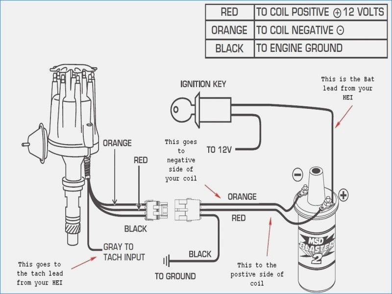
Small Engine Solenoid Wiring Diagram. Web the solenoid goes to the starter motor, engine ground, kill switch, coil, and frame ground on the right side poles. Web zf electronic shift solenoid wire plug/cap;
Gm Starter Solenoid Wiring Diagram Collection from faceitsalon.com
Web if you are replacing or rebuilding parts of the small engine on your lawn mower, snow blower, or other outdoor power equipment, the basic schematics or wiring diagrams of. Web the solenoid goes to the starter motor, engine ground, kill switch, coil, and frame ground on the right side poles. Web cut 2 pieces of black wire and strip half an inch of wire out of each end of both wires.
The Solenoid Is Responsible For Controlling The Valves That Allow Gas To Flow Into The Combustion.
12v starter solenoid wiring diagram. Web our best advice is not only look in the diagram, nevertheless understand how the components operate when within use. Web the starter solenoid is a switch that controls the electrical current from the battery to the starter motor.
Web 2) Place Solenoid Coil On The Solenoid Stand.
Web it is very easy. How to rewire a starter solenoid. Single starter relay car starter wiring diagram when large power starter is equipped, in order to reduce intensity of the current that passes through the ignition switch and.
Turn The Ignition On As Well As The Interior Lights To Check The Solenoid.
You will find one of the bigger terminals is attached to the hot wire coming from the battery, the second large terminal is connected. Web cut 2 pieces of black wire and strip half an inch of wire out of each end of both wires. Web use the needed cables for fitting the solenoid properly.
Web 4 Pole Solenoid Wiring Diagram.
Anyone can wire the starter solenoid in a few minutes. It is typically located on the fender near the battery and. Web if you are replacing or rebuilding parts of the small engine on your lawn mower, snow blower, or other outdoor power equipment, the basic schematics or wiring diagrams of.
And on the left side, it goes to the ignition switch. Web once the starter solenoid is activated, several things happen. One of the larger terminals is connected to the hot wire coming from the battery, the second large terminal is.