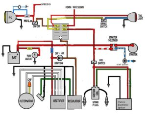
Wire the magneto to the switch. As long as you follow the ladder diagram and take it one wire at a time its simpleThis.
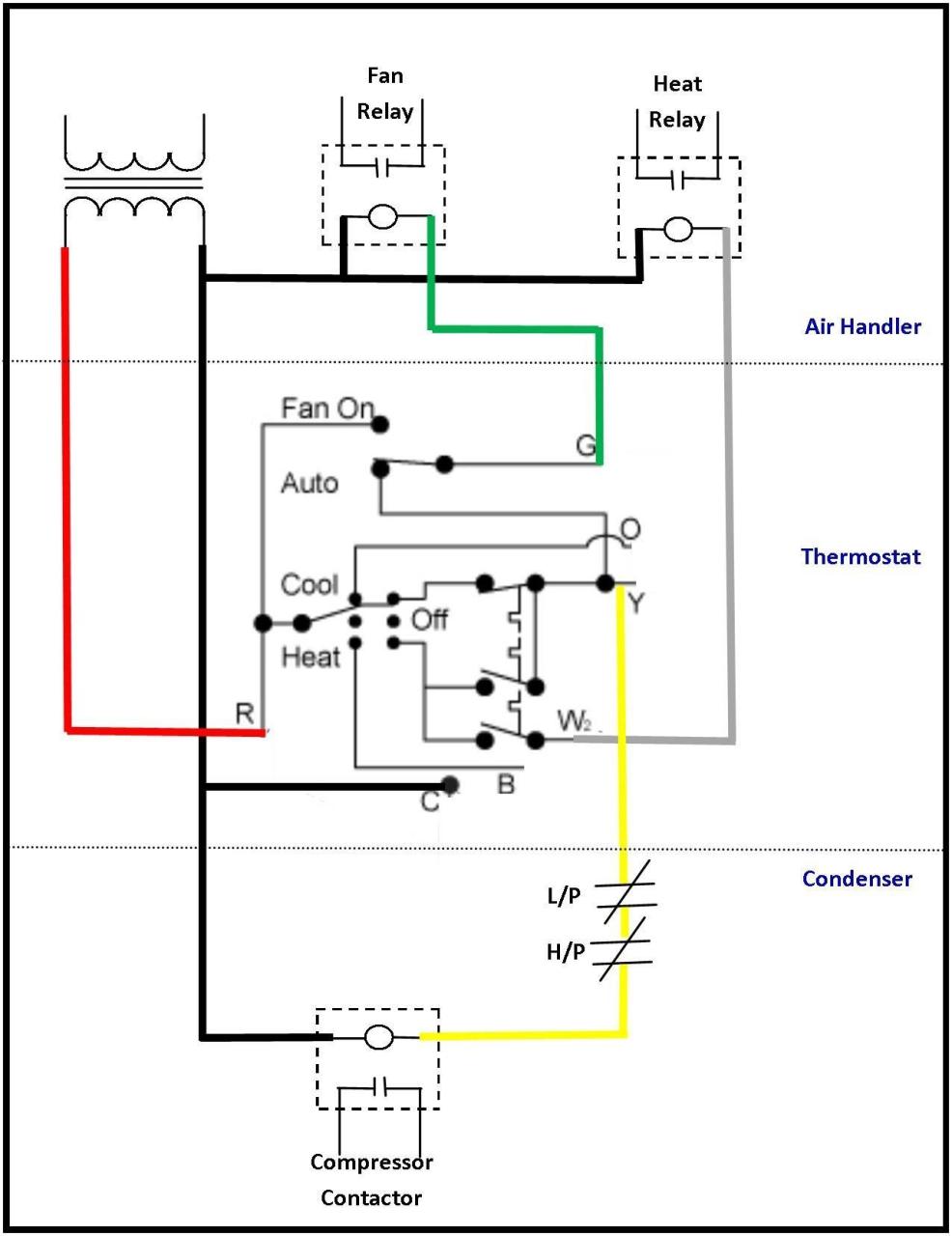
50 Luxury 90340 Relay Wiring Diagram Thermostat Wiring Electrical Circuit Diagram Electrical Wiring Diagram
Start stop push button wiring diagram You will want a comprehensive professional and easy to understand Wiring Diagram.

Start Stop Push Button Wiring Diagram. Typical wiring diagrams for push button control stations 7 start stop control wiring diagrams single station with motor stopped pilot light l1 start l2 i 1 stop 2 oi 3 n w o l. In this episode we will learn how emergency push buttons are wired the correct way. This video is a step by step explanation of wiring Start Stop basics.
However it doesnt mean link between the wires. Push On Start Stop Switch Wiring Diagram All Wiring Diagram Start Stop Push Button Wiring Diagram. These directions will probably be easy to understand and apply.
Wiring diagram single motor with Start Stop switch Basic control motor to get start or stop the motor use a push button switch as a trigger a motor. Provide voltage by connecting the battery. Wiring Diagrams Non-Illuminated Contacts Wiring Illuminated Contacts Wiring SSA-EB1P-02 SSA-EB1MP-02 2 normally closed NC 12 11 21 22 SSA-EB1PL1-02 SSA-EB1ML1P-02 2 normally closed NC 12 11 21 22 X1 X2 LED24V SSA-EB1P-04 SSA-EB1MP.
Obtain a circuit diagram. They are used in applications which do not require undervoltage protection. Locate all components that need wiring.
A circuit is generally composed by many components. There are just two things which are going to be found in any Push Button Starter Switch Wiring Diagram. It includes directions and diagrams for different kinds of wiring methods along with other items like lights windows and so forth.
And why not the other wayConsider support via donation from the link u. Wiring diagrams sometimes called main or construc-. Wiring Diagram contains several detailed illustrations that present the relationship of varied things.
It uses three contactors an overload relay one auxiliary contact block a normally open start pushbutton a normally closed stop pushbutton an on-delay timer of 0-20 seconds and a. Injunction of 2 wires is usually indicated by black dot in the intersection of 2 lines. Its meant to help each of the average user in developing a proper system.
We need a contactor an auxiliary contact block an overload relay a normally open start pushbutton a normally closed stop pushbutton and a power supply with a fuse Not shown on the picture. Typical Wiring Diagrams For Push Button Control Stations 7 Start-Stop Control Wiring Diagrams SINGLE STATION -WITH MOTOR STOPPED PILOT LIGHT L1-_ START L2 I 1 STOP 2 OI 3 n wOL. These guidelines will probably be easy to grasp and use.
So study these symbols carefully please. The other thing that you will find a circuit diagram would be lines. The first component is emblem that indicate electric component from the circuit.
2 4 6 M 1 OL 3-Phase Motor. Wiring diagram single motor with start stop switch basic control motor to get start or stop the motor use a push button switch as a trigger a motor. Wiring diagrams do not show the operating mechanism since it is not electrically controlled.
Connect the switch to the Solenoid. –c I m NC. 2-Wire Control 3-Wire Control Start Stop 3 2 1 1 3 Not for use with Auto Reset OL Relays.
To accomplish this splice or double a 12-gauge jumper wire off of the pink wire at the ignition switch connection and take that jumper wire over to one side of the push. The application is loaded to make it easier for you to learn about electricity that helps you in knowing the electrical circuit many diagrams about start stop wiring push button diagrams that you can learn in full the categories in this application include 1 start stop push button 2 start stop the wiring diagram. T w 6.
According to earlier the lines at a Start Stop Push Button Wiring Diagram signifies wires. Later in this text we will be working with actual applications and line diagrams. Wiring diagram comes with a number of easy to stick to wiring diagram guidelines.
These guidelines will probably be easy to grasp and use. Connect the switch to ground. Diagram emergency stop push button wiring diagram full version hd quality wiring diagram.
I have got myself an old IXL Capitol lathe a while ago and I just recently got around to removing the old gigantic three phase motor and making a pedestal up to mount a modern single phase motor so. Wiring Diagram comes with a number of easy to stick to Wiring Diagram Guidelines. At times the wires will cross.
The following diagram is shown for a 3-wire control with 24 VDC control voltage. Typical Wiring Diagrams For Push Button Control Stations 7 Start-Stop Control Wiring Diagrams SINGLE STATION -WITH MOTOR STOPPED PILOT LIGHT L1-_ START L2 I 1 STOP 2 OI 3 n wOL. PILOT LIGHT L2 4 2 3 PILOT LIGHT START STOP Bulletin 1495 normally closed auxiliary contacts are required.
Everything rides on circuit thats being constructed. These guidelines will probably be easy to grasp and use. WIRING DIAGRAMS Bulletin 609 manual starters are operated by START-STOP push buttons mounted on the front of the starter.
How to wire an Emergency Stop button. The picture shows the same arrangement. Vfd is a short form of variable frequency drive or variable voltage variable frequency driveThe VFDs are working based on changing the input frequency and input voltage of the motor we can change.
You can convert your car to the push-button start and add a keyless ignition by replacing the hot wires with a switchThe hot-wiring process involves two wire ends touching each other to produce ignition whereas a push-button start will use a switch instead. Figure 1 is a typical wiring diagram for a three-phase mag- Start stop push button station wiring diagram Start Stop Push button Station Wiring Diagram Unique Triumph Spitfire Rebuild. How to wire a lawnmower ignition switch step by step.
Push Button Start Stop Switch Wiring Diagram Electricity Site Push Button Starter Switch Wiring Diagram. Wiring a push-button stop start switch.

Craftsman Riding Mower Electrical Diagram Wiring Diagram Craftsman Riding Lawn Mower I Need One For Craftsman Riding Lawn Mower Lawn Mower Riding Mower

3 Phase Split Ac Wiring Diagram Ac Wiring Air Compressor Pressure Switch Split Ac

Dol Starter Panel Wiring Diagram Save Start Stop And Motor Electrical Circuit Diagram Circuit Diagram Electric Circuit

5 Pin Cdi Wiring Diagram Diagram Electrical Circuit Diagram Wire

60 Beautiful Motor Starter Wiring Diagram Electrical Circuit Diagram Circuit Diagram Electrical Wiring Diagram

Split Ac Full Electric Wiring Diagram Fully4world Fully4world Air Conditioning System Design Refrigeration And Air Conditioning Hvac Air Conditioning

Cdi Wiring Diagram Motorcycle Wiring Kill Switch Electrical Wiring Diagram

Air Conditioner C S R Wiring Diagram Compressor Start Full Wiring Fully4 Air Conditioner Maintenance Refrigeration And Air Conditioning Hvac Air Conditioning

Stop Start Wiring Diagram For Air Compressor With Overload Google Search Teknik Listrik Rangkaian Elektronik Teknologi

Installation Of Single Pole 3 Way 4 Way Switches Wiring Diagram Electrical Wiring Home Electrical Wiring Electrical Switch Wiring

Lewmar Windlass Wiring Diagram Upgrade Windlass Power Wiring Of Lewmar Windlass Wiring Diagram With Windlass Wiring Diagram For Windlas Diagram Power Wire Wire

3 Phase Start Stop Wiring Diagram Circuit Diagram Electrical Circuit Diagram Electrical Diagram

45 Unique Reversing Motor Starter Wiring Diagram Electrical Circuit Diagram Circuit Diagram Electrical Symbols

Unique Yamaha Moto 4 Wiring Diagram Yamaha Golf Carts Electric Golf Cart Diagram
Unique Wiring Diagram For Chinese 110cc Atv Wiring Diagram Chinese Atv Wiring Diagrams Roketa 11 Motorcycle Wiring Electrical Diagram Electrical Wiring Diagram

Push Button Ignition Switch Wiring Diagram New Boat Wiring Kill Switch Electrical Wiring Diagram

Unique Wiring Diagram For Chinese 110cc Atv Wiring Diagram Chinese Atv Wiring Diagrams Roketa 11 Motorcycle Wiring Electrical Diagram Electrical Wiring Diagram

Best Bosch Relay Wiring Diagram 5 Pole Electrical Outlet Symbol 2018 Electrical Circuit Diagram Light Switch Wiring Electrical Wiring Diagram

110cc Chinese Atv Wiring Diagram Schaferforcongressfo Motorcycle Wiring Pit Bike Trailer Wiring Diagram