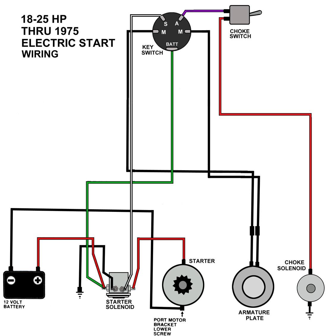
12 volt solenoid wiring diagram collections of 12 volt solenoid wiring diagram collection. Wiring diagram a 12 volt automotive relay best new 12v starter.

Yanmar Solenoid Wiring Diagram Wiring In 2020 Boat Wiring Kill Switch Electrical Wiring Diagram
These directions will be easy to understand and implement.

Starter relay ford starter solenoid wiring diagram. Wiring diagram for ford starter relay save 1984 ford f150 wiring inspirational starter relay wiring diagram electrical outlet building wiring representations show the approximate places and also interconnections of receptacles lights as well as long term electric services in a building. Spdt relay wiring diagram wiring diagrams click 12 volt relay wiring diagram. The role of starter relay is to control the high current with low current protect the ignition switch and reduce the line drop of the starter solenoid switch.
Ford starter solenoid wiring diagram wiring diagram is a simplified normal pictorial representation of an electrical circuit it shows the components of the circuit as simplified shapes and the capability and signal friends amongst the devices. 4 wire starter solenoid diagram auto electrical wiring diagram starter relay wiring diagram. The single relay controlled starter solenoid wiring diagram is as shown in the following picture.
If not the arrangement will not work as it should be. Winch solenoid wiring diagram 12 volt for boat how wire a trailer. It includes directions and diagrams for different types of wiring strategies along with other items like lights home windows and so forth.
Ford starter solenoid wiring diagram 1988 ford starter solenoid wiring diagram ford 8n starter solenoid wiring diagram ford bronco starter solenoid wiring diagram every electric structure consists of various unique components. Wiring diagram comes with a number of easy to follow wiring diagram guidelines. Each component should be set and connected with different parts in specific manner.
4 pole solenoid wiring diagram download. Wiring diagram starter solenoid refrence elegant 4 pole solenoid. These solenoids are typically the first thing that goes out.
It really is meant to assist all the common person in creating a correct system. It s essentially a big relay which provides power from the battery to the starter motor when the ignition key is turned over starting the vehicle. Ignition relay wiring diagram fresh starter solenoid wiring diagram.
Wiring diagram consists of several in depth illustrations that show the relationship of varied products. 4 pole starter solenoid wiring diagram collections of wiring diagram for phase failure relay new starter relay wiring. A ford starter solenoid is one of the key components to the starting system of most older ford vehicles.
Wiring diagram relay starter motor fresh ignition relay wiring.

Starter Solenoid Wiring Diagram Ignition Motorcycle Wiring Electrical Wiring Diagram Alternator Working

Small Engine Solenoid Wiring Diagram In 2020 Small Engine Electrical Diagram Wire

Ford On Ford Solenoid And It Keeps All The Factory Connections At The Starter Starter Motor Automotive Mechanic Engineering

56317d1340581640 Ford 4 Terminal Solenoid Wiring Jpg 767 477 Tractors Car Mechanic Automotive Technician

Wiring Diagram For A Starter Solenoid Post Date 19 Nov 2018 78 Source Http Readingrat Net W Electricity Electrical Diagram Automotive Electrical

641fg 1971 Ford F100 Jumping Battery Terminal Starter Relay Solenoid Auto Electrico Ford Autos

Sample Image Ford Starter Selenoid Wiring Diagram 1971 Ford Starter Solenoid Wiring Diagram Schematic Ford Starter Sel Ford F150 Remote Car Starter Car Starter

Starting System Diagram Starter Motor Motorcycle Wiring Automotive Repair

35 Awesome Ford Starter Relay Wiring Diagram In 2020 Automotive Mechanic Truck Repair Automotive Repair

Pushbutton Starter Wiring For 9n Yesterday S Tractors 8n Ford Tractor Tractor Photos Old Tractors

Picture Ford Starter Selenoid Wiring Diagram Ford F250 Starter Solenoid Wiring Diagram 4 Pole Lovely Post Bookingritzcarlton Info Ford F150 Ford Diagram

Wire Diagram Ford Starter Solenoid Relay Switch Starter Electrical Diagram Mower

1994 Ford F 250 Starter Solenoid Wiring Diagram Moreover 1996 F150 Free Picture Schematic Ford F250 Ford Bronco Ford F150

Image Ford Starter Selenoid Wiring Diagram Solenoid Wiring Diagram 10 13 Asyaunited De U2022solenoid Control R Diagram Paint Colors Benjamin Moore Line Diagram

Picture Of Ford Starter Selenoid Wiring Diagram 1990 Ford F150 Starter Solenoid Wiring Diagram Bestharleylinks Info Rh Bestharleylinks Info 1990 Ford F Bookin Ford Explorer Accessories Ford Trucks Ford F150

Starter Solenoid Wiring Diagram Starter Motor Ford Tractors Starter

10 Small Engine Starter Switch Wiring Diagram Engine Diagram Wiringg Net In 2020 Boat Wiring Kill Switch Trailer Wiring Diagram

Perfect Ford Starter Selenoid Wiring Diagram Ford F150 Starter Wiring Diagram Vtl Cannockpropertyblog Uk U2022 Rh Vtl Cannockpropertyblog Uk 1994 F150 Starter W In 2020 Ford F150 F150 Diagram

Image Result For Mopar Starter Relay Wiring Diagram Mopar Relay Electrical Wiring Diagram

