Device wiring basics. The diagram below shows the power entering the circuit at the grounded outlet box location then sending power up to the switch and a switched leg back down to the outlet.
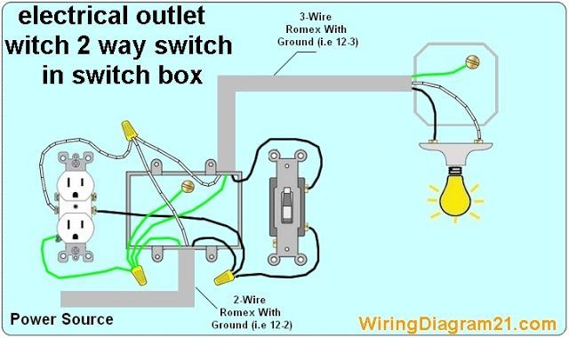
Image Result For How To Wire A 2 Way Light Switch And Light Fixture With Continuing Circuit Light Switch Wiring Outlet Wiring Electrical Outlets
Making safe long lasting connections requires properly preparing the circuit wires that will connect to the device and secure each wire to the correct terminal.

Switch and outlet wiring diagram. These electrical wiring diagrams show typical connections. The switch takes the hot from the middle receptacle here and 3 wire cable runs from there to the new switch location. The hot source at the outlet is spliced to the black wire running to the switch and the hot wires running to the other outlets in.
To connect the switches simply score the wire with your wire stripper and push the insulation to expose about 3 4 in. The white wire is marked black on both ends to identify it as hot. In this updated diagram 3 wire cable runs between the receptacle and switch and the red cable wire is used to carry the hot source to the switch.
They can work in conjunction with one another or they can be connected and used independent of each other. The neutral is connected to the neutral silver terminal. For wiring in series the terminal screws are the means for passing voltage from one receptacle to another.
Wall outlet switch wiring diagram. Outlet wiring for a table lamp or a floor light fixture. Connect the last switch in the usual manner looping the wire around the screw in a clockwise direction.
The switch receptacle combo device is set up like a duplex receptacle but has a 15a single pole switch in one half and a single 15a 125v receptacle in the other half. Wiring electrical outlets properly called receptacles and switches involve many of the same basic techniques. Any break or malfunction in one outlet will cause all the other outlets to fail.
The single pole switch has a neutral conductor for future electronic controls such as a timer or a wifi switch. The break away fin tab is intact therefore line hot is connected to the only one brass terminal on line side. The switch load brass terminal and neutral is connected to the light bulb.
The black cable wire runs to the sw1 connecting it to the hot on the top half of the split outlet. Instead of running a separate pigtail from the hot wire to each switch just leave the hot wire extra long. Here a switch has been added to control an existing receptacle.
To wire multiple outlets follow the circuit diagrams posted in this article. Multiple outlet in serie wiring diagram. In this simple wiring diagram the combo switch outlet is connected to the 120v ac supply through cb.
Wiring diagram of a switched electrical receptacle outlet and an unswitched electrical receptacle outlet with the power entering the switched outlet electrical box from the circuit breaker panel.

Wiring Diagrams To Add A Receptacle Outlet Home Electrical Wiring Light Switch Wiring Electrical Wiring

Wiring Diagram For House Outlets Http Bookingritzcarlton Info Wiring Diagram For House Outlets Outlet Wiring Light Switch Wiring Wire Switch

2 Way Switch Outlet Wiring Diagram Box Cablage Electrique Electricite Prise Electrique

Wiring A Switched Outlet Wiring Diagram Http Www Electrical Online Com Wiring A Switched Outlet Diagram Home Electrical Wiring Diy Electrical Outlet Wiring

Switch Controlled Outlet Wiring Diagram Bing Images Outlet Wiring Light Switch Wiring Wire Switch

Diagram For Two Switches Controlling One Split Outlet Light Switch Wiring Wire Switch Electrical Wiring

Gfci Receptacle And Switch Same Box Electrical Wiring Home Electrical Wiring Outlet Wiring

Wiring Diagrams To Add A New Light Fixture Light Switch Wiring 3 Way Switch Wiring Wire Switch

Wiring A Outlet Switch Combo With Two Electrical Sources Light Switch Wiring Wire Switch Home Electrical Wiring

Wiring Switched Split Outlet With Source And Receptacle First Complies With Nec 2011 In 2020 Outlet Wiring Light Switch Wiring Wire Switch

Light Switch And Outlet In Same Box Light Switch Wiring Diy Electrical Home Electrical Wiring

Split Switched Outlet Wiring Diagram Outlet Wiring Basic Electrical Wiring Home Electrical Wiring

Wiring Diagrams To Add A New Light Fixture Light Switch Wiring 3 Way Switch Wiring Wire Switch

How To Wire Switches Wire Switch Outlet Wiring Home Electrical Wiring

Combination Switch Receptacle Wiring Diagram Wiring Diagram Combo Switch Light Switch Wiring Wire Switch Electrical Wiring Outlets
Switch And Receptacle Same Box Light Switch Wiring Electrical Wiring Home Electrical Wiring

Electrical Wiring Diagram Add Outlet Gif 500 327 Light Switch Wiring Home Electrical Wiring Installing A Light Switch

Wiring Diagrams To Add A New Light Fixture Wire Switch Light Switch Wiring House Wiring

Wiring Diagrams For Switch To Control A Wall Receptacle Electrical Switches Wiring A Plug Home Electrical Wiring