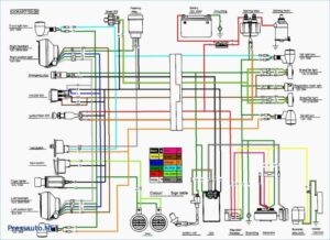
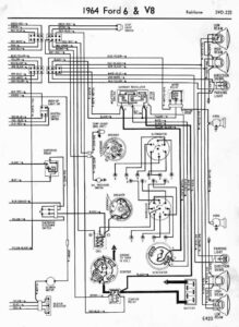
Yamaha outboard wiring diagram pdf collections of johnson outboard wiring diagram pdf wiring diagram collection. It reveals the elements of the circuit as simplified forms as well as the power and signal connections in between the tools.

Fuel Gauge Wiring Diagram Car Gauges Gauges Boat
Variety of yamaha outboard tachometer wiring diagram.

Yamaha outboard tachometer wiring diagram. Yamaha outboard wiring diagram wire center. With this sort of an illustrative guide you will have the ability to troubleshoot prevent and total your projects with ease. Johnson outboard wiring diagram pdf wiring diagram collection.
View and download yamaha ff owner s manual online. Not only can you find different diagrams but you can also get step by step instructions to get a. We are your trusted online solution when it comes time for your next catalog lookup regarding yamaha outboard parts and diagrams.
Collection of yamaha outboard wiring diagram pdf. A wiring diagram is a simplified standard photographic representation of an electric circuit. Mercruiser tachometer wiring schematic diagram yamaha outboard wiring harness diagram.
Ff outboard motor pdf manual download. The new yahama tachometer and rigging harness s arrived 13 mar after studying the wiring rigging diagram downloaded from the internet i installed the tach to mate up w my yamaha f70la 4 stroke outboard. Yamaha outboard tachometer wiring diagram you will need a comprehensive expert and easy to comprehend wiring diagram.
Fld fb flb fd1 fld1 fb1 flb1. Yamaha outboard wiring diagram pdf a beginner s overview of circuit diagrams. A wiring diagram is a streamlined traditional photographic depiction of an electric circuit.
Wiring diagram not just offers detailed illustrations of everything you can perform but additionally the methods you ought to follow while performing so. Yamaha outboard wiring diagram inspirational yamaha 703 remote. 2008 yamaha 50 2 stroke outboard wiring manual.
A first check out a circuit layout may be complicated however if you can check out a metro map you could check out schematics.

Electrical Wiring Mercury Outboard Trim Gauge Wiring Diagram How To Install Fo Johnson Ignition Switch Boat Wiring Electrical Wiring Diagram Mercury Outboard

Honda Wiring Diagram Symbols Bookingritzcarlton Info Electrical Wiring Diagram Diagram Motorcycle Wiring

Where To Hook Tach To On Ignition Key Switch On An Omc Evinrude For Wiring Diagram For Boat Ignition Switch In Tachometer Wiring Tachometer Diagram Boat Wiring

Yamaha Outboard Electrical Wiring Diagram Wiringdiagram Org Electrical Wiring Diagram Boat Wiring Electrical Wiring

Bosch Relay Schematic Google Search Diagram Outboard Tachometer

Yamaha Outboard Main Harness Wiring Diagram The Wiring Diagram Trailer Plans Outboard Automotive Repair

Mercury Outboard Wiring Diagrams Mastertech Marin Wiring Diagram Outboard Mercury Outboard Diagram

Mercruiser 140 Engine Wiring Diagram And Mercruiser Ignition Wiring Diagram Schematics Online In 2020 Diagram Wire Outboard

Mercury Outboard Wiring Schematic Have A 1998 50hp Mercury Outboard Motor Ser 0g6291554 Ineed Mercury Outboard Outboard Outboard Motors

Yamaha Outboard Wiring Harness Diagram Electrical Wiring Diagram Boat Wiring Outboard

Boat Trim Gauge Wiring Diagram Nilza

12 Marine Power Engine Wiring Diagram Engine Diagram Wiringg Net In 2020 Diagram Wire Electrical Wiring Diagram

Evinrude Trim Gauge Wiring Diagram Google Search Mercury Outboard Outboard Diagram

Yamaha Engine Diagram Quality Di 2020 Dinding Kartun Desain

New Wiring Diagram Car Indicators Motorcycle Wiring Electrical Diagram Electrical Wiring Diagram

Mercury Outboard Wiring Diagram Mercury Outboard Outboard Boat Wiring

Engine Ground Diagram Yamaha In 2020 Outboard Diagram Yamaha


