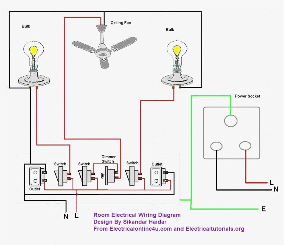
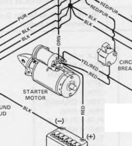
Wiring multiple outlets in a series in this diagram wall outlets are wired in a row using the terminal screws to pass voltage from one receptacle to the next. Receptacle wiring in the diagram below a 2 wire nm cable supplies line voltage from the electrical panel to the first receptacle outlet box.

Wiring Diagram For House Light Switch Electrical House Wiring Hindi 2 Basic Residential Diagrams Dia
Any break or malfunction in one outlet will cause all the other outlets to fail.

Beginner residential electrical outlet wiring diagram. A wiring diagram is a simple visual representation of the physical connections and physical layout of an electrical system or circuit. For wiring in series the terminal screws are the means for passing voltage from one receptacle to another. Specific dedicated circuits are identified for larger equipment which requires a higher amount of electrical power.
Wire a trailer how to wire a trailer i will show you basic concepts and color codes for a 4 wire 6 wire and 7 wire connector used for wiring trailers. Wiring an ungrounded polarized outlet. This outlet is commonly used for a heavy load such as a large air conditioner.
Multiple outlet in serie wiring diagram. General materials and wiring techniques for residential wiring sam maltese shows some general information regarding house wiring. 1 for each hot and neutral wire entering the box 1 for all the ground wires combined 1 for all the cable clamps combined if any 2 for each device switch or outlet but not light fixtures multiply the total by 2 for 14 gauge wire and 2 25 for 12 gauge wire to get the minimum box size required in cubic inches.
Wiring a 20 amp 240 volt appliance receptacle. To wire multiple outlets follow the circuit diagrams posted in this article. This circuit originates from the breaker box containing a 2 pole 30 amp breaker.
For example wiring for 20 amp circuits is 12 gauge which is heavier than the 14 gauge wiring used for 15 amp circuits. The outlet should be wired to a dedicated 20 amp 240 volt circuit breaker in the service panel using 12 2 awg cable. Wire size is given in its gauge number.
The lower the gauge the larger the wire and the more current it can handle. The 3 prong dryer wiring diagram here shows the proper connections for both ends of the circuit. This size breaker requires a minimum of a 10 gauge wire so this wire used would be a 10 2 with ground.
Wire a dryer outlet how to wire a dryer outlet how to wire a 3 prong dryer outlet and a 4 prong dryer outlet. Residential wiring diagrams area a complete set of plans with detailed information about the electrical systems for each room. Wires running inside nm cable bx cable or conduit are sized according to each circuit s amperage.
Computer connection diagram computer connection diagram how to hook up a computer. Wiring outlets together using the device terminals instead of a pigtail splice as shown in the next diagram can create a weakest link problem. How a 3 wire dryer outlet circuit looks.
This repeats until the end of the chain. With this wiring both the black and white wires are used to carry 120 volts each and the white wire is wrapped with electrical tape to label it hot. The black wire line and white neutral connect to the receptacle terminals and another 2 wire nm that travels to the next receptacle.

Wiring Diagram For House Outlets Http Bookingritzcarlton Info Wiring Diagram For House Outlets Outlet Wiring Wiring A Plug Home Electrical Wiring

Simple Home Electrical Wiring Diagrams Home Electrical Wiring Light Switch Wiring Electrical Wiring Diagram

Basic House Wiring Home Electrical Wiring Basic Electrical Wiring House Wiring

Wiring A Light Switch Basic Electrical Wiring Electrical Wiring Electrical Switch Wiring

California Mobile Home Kitchen Electrical Requirements Yahoo Image Search Results House Wiring Basic Electrical Wiring Electrical Wiring

Wiring Diagrams For Electrical Receptacle Outlets Outlet Wiring Wiring A Plug Home Electrical Wiring

Split Plug Wiring Diagram Outlet Wiring House Wiring Home Electrical Wiring

House Wiring For Beginners Diywiki House Wiring Diagram Circuit Diagram

Double Outlet Box Wiring Diagram In The Middle Of A Run In One Box Outlet Wiring Electrical Wiring Outlets Electrical Wiring

Click For Bigger Picture Electrical Circuit Diagram Home Electrical Wiring Basic Electrical Wiring

Wiring Diagram For House Lighting Circuit Http Bookingritzcarlton Info Wiring Diagram For House Light House Wiring Domestic Wiring Electrical Wiring Diagram

Wiring Diagrams To Add A Receptacle Outlet Home Electrical Wiring House Wiring Electrical Wiring

Wiring Diagram For House Outlets Http Bookingritzcarlton Info Wiring Diagram For House Outlets Outlet Wiring Light Switch Wiring Wire Switch

Basic Home Electrical Wiring Diagrams File Name Basic Household Electrical Circuit Diagram Basic Electrical Wiring Electrical Wiring Diagram

Electrical Outlet Wiring Diagram Outlet Wiring Home Electrical Wiring Electrical Wiring

New Split Consumer Unit Wiring Diagram Diagram Diagramtemplate Diagramsample Electrical Circuit Diagram Basic Electrical Wiring Circuit Diagram

Wiring Diagrams Multiple Receptacle Outlets Outlet Wiring Home Electrical Wiring Gfci

Electrical Technology Home Electrical Wiring Basic Electrical Wiring Electrical Wiring


