Wiring Diagram For Electric Brakes On A Trailer. Please ensure you have the correct. Brake controller installation starting from scratch etrailer com.
Wiring Diagram For Trailer Lights And Electric Brakes Trailer Wiring from trailer-wiring-diagram.com
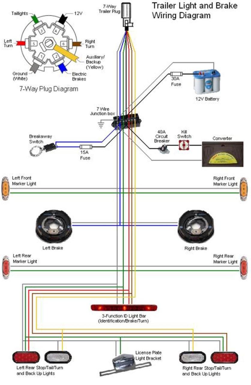
Trailer brake control wiring diagram. The steps for wiring electric trailer brakes are as follows: Sometimes, the cables will cross.
4 Pin Trailer Wiring Install Diagram Guide.
Breakaway brakes and battery disconnect switch t b 320. White wire provides ground for completion of the circuit. E70 trailer wiring no brake lights on oem kit electrical system bimmersport co nz.
Loosen The Screw On The Back Of The Brake Assembly And Pull Out The.
Trailer wiring diagrams etrailer com. The following diagram is a general guide for wiring common brake controllers into cars. Trailer wiring diagram trailers in denver co dealer for enclosed and flatbed utiliity at all american.
Please Ensure You Have The Correct.
Trailer wiring brake diagram brakes flatbed. Trailer wiring diagram 4 5 6. Trailer wiring diagram 4 5 6 7 pin wire with brakes lights etechnog installing electric brakes on your trailer r and p carriages s als in chicago tow hitch trailer brake.
The Actual Distinction Between The Wires Will.
September 23, 2021 by wiring digital. The manual adjusting brake will not have this wire running across the inside of the assembly. Sometimes, the cables will cross.
12V Tow Diagram Jpg 1000 X 1530 28 Trailer Light Wiring Utility Trailer Trailer Wiring Diagram.
On the 1 o’clock side it will have a banjo looking fitting (shown to the left). Auxiliary connection is optional, it may be connected to any 12v to 24v constant power source or left unconnected. Electric trailer brake wiring diagram with breakaway actuator k71 hydrastar breakaway psi etrailer ufp electrohydraulic.