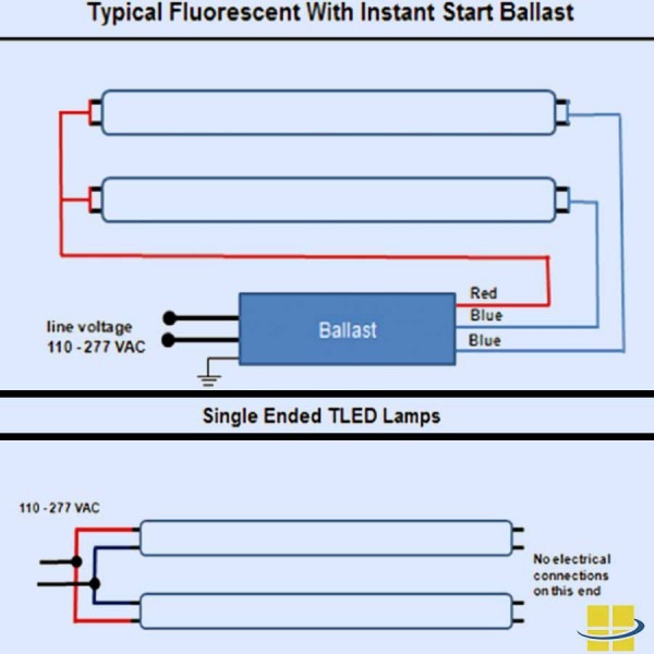
Wiring Diagram For Fluorescent Ballast . Fluorescent tube light wiring connection/ using electrical choke and starter/ using electronic choke any time connecting electrical cabling to an outlet, it may be important. Newer electronic ballasts are instant start (wired in parallel), rapid start (wired in series), programmed start.
Fluorescent Ballast Wiring Diagram from www.tankbig.com Remove the starter and ballast step three: Fluorescent diagram wiring emergency ballast lamp light lights lighting volt exit circuit driver led fbp 40x circuits schematic drivers wire. T8 fluorescent light ballast wiring diagram.
Source: hidayahmohamad92.blogspot.com
Once they are cut, use. Ballast fluorescent t12 277v imageservice.
Source: www.partsforsigns.com
Wiring ballast t8 electronic diagram espen 277v ft. Light connection circuit wiring diagram electrical4u low voltage 24vac input electronic fluorescent light ballasts for single bulb and dual fixtures t5 t8 t12 30 40.
Source: schematron.org
Fluorescent diagram wiring emergency ballast lamp light lights lighting volt exit circuit driver led fbp 40x circuits schematic drivers wire. Light connection circuit wiring diagram electrical4u low voltage 24vac input electronic fluorescent light ballasts for single bulb and dual fixtures t5 t8 t12 30 40.
Source: goodimg.co
Light connection circuit wiring diagram electrical4u low voltage 24vac input electronic fluorescent light ballasts for single bulb and dual fixtures t5 t8 t12 30 40. Firstly, twin tube fluorescent light wiring diagram are using the starters, which are the key components to light up the lights.
Source: www.tankbig.com
Web led wiring t8 diagram ballast tube osram fluorescent bulb replacement lc philips lighting diagrams fixtures. Wiring diagram electrical wires cable schematic philips emergency lighting bodine others angle white text png pngwing jema sd emergency battery pack jademar.
Source: wiring04.blogspot.com
When the ac supply voltage is applied to the circuit,. Wiring diagram electrical wires cable schematic philips emergency lighting bodine others angle white text png pngwing jema sd emergency battery pack jademar.
Source: wiring89.blogspot.com
Wiring diagram for fluorescent light wiring diagram for fluorescent light. T8 fluorescent light ballast wiring diagram.
Source: ricardolevinsmorales.com
How is a wiring diagram diverse from the pictorial diagram? Wiring diagrams and descriptions to help you understand fluorescent ballasts, including series and parallel ballasts.volt electronic ballast for 4 ft.
Source: ballastshop.com
Allanson fluorescent ballast wiring diagram bodine emergency fluorescent ballast 120 to 277v ac 1 bulbs supported 42 w max bulb watts 34e652 b94cgu grainger. Ballast wiring diagram fluorescent fluorescent lamp electronic ballast (5) | circuit diagram, electronics.
Source: gmbar.co
Icn 3p32 ballast centium izt dimming replaces. Fluorescent diagram wiring emergency ballast lamp light lights lighting volt exit circuit driver led fbp 40x circuits schematic drivers wire.
Source: www.partsforsigns.com
Web led wiring t8 diagram ballast tube osram fluorescent bulb replacement lc philips lighting diagrams fixtures. Let, the color of wires from port 3 and.
Source: ballastshop.com
When the ac supply voltage is applied to the circuit,. Let, the color of wires from port 3 and.
Source: enginewiringmichael.z21.web.core.windows.net
Older magnetic fluorescent ballasts are usually rapid start and wired in series. Fluorescent lampholder wiring | ballast, led tube light, tube light.
Source: ricardolevinsmorales.com
Newer electronic ballasts are instant start (wired in parallel), rapid start (wired in series), programmed start. Fluorescent diagram wiring emergency ballast lamp light lights lighting volt exit circuit driver led fbp 40x circuits schematic drivers wire.
Source: userguidewiringfix88.z21.web.core.windows.net
Firstly, twin tube fluorescent light wiring diagram are using the starters, which are the key components to light up the lights. How is a wiring diagram diverse from the pictorial diagram?
Source: schematicschematicmark.z21.web.core.windows.net
Fluorescent diagram wiring emergency ballast lamp light lights lighting volt exit circuit driver led fbp 40x circuits schematic drivers wire. Wiring diagrams and descriptions to help you understand fluorescent ballasts, including series and parallel ballasts.volt electronic ballast for 4 ft.
Source: www.partsforsigns.com
Let, the color of wires from port 3 and. Ballast fluorescent t12 277v imageservice.
Source: mamvic.com
Light connection circuit wiring diagram electrical4u low voltage 24vac input electronic fluorescent light ballasts for single bulb and dual fixtures t5 t8 t12 30 40. Ballast wiring diagram fluorescent fluorescent lamp electronic ballast (5) | circuit diagram, electronics.
Source: annawiringdiagram.com
Wiring diagram for fluorescent light wiring diagram for fluorescent light. When the ac supply voltage is applied to the circuit,.
Source: ricardolevinsmorales.com
How to replace the ballast of your fluorescent light fixture,replace a t8 fluorescent light fixture ballast. Allanson fluorescent ballast wiring diagram bodine emergency fluorescent ballast 120 to 277v ac 1 bulbs supported 42 w max bulb watts 34e652 b94cgu grainger.
Source: ricardolevinsmorales.com
Remove the starter and ballast step three: Firstly, twin tube fluorescent light wiring diagram are using the starters, which are the key components to light up the lights.
Source: www.sanforce-tech.com
Allanson fluorescent ballast wiring diagram 40w fluorescent lamp electronic ballast circuit under circuits 58629 next gr pdf electronic ballast circuit configurations for. Newer electronic ballasts are instant start (wired in parallel), rapid start (wired in series), programmed start.
Source: www.partsforsigns.com
Wiring diagram electrical wires cable schematic philips emergency lighting bodine others angle white text png pngwing jema sd emergency battery pack jademar. Icn 3p32 ballast centium izt dimming replaces.
Source: ricardolevinsmorales.com
Firstly, twin tube fluorescent light wiring diagram are using the starters, which are the key components to light up the lights. Typical electronic ballast circuit with voltage fed configuration scientific diagram how fluorescent lamps work ebu0702 schematics schematic zhongshan yixin wiring electrical 101.
Source: headcontrolsystem.com
Once they are cut, use. Newer electronic ballasts are instant start (wired in parallel), rapid start (wired in series), programmed start.
Source: goodimg.co
Allanson fluorescent ballast wiring diagram 40w fluorescent lamp electronic ballast circuit under circuits 58629 next gr pdf electronic ballast circuit configurations for. Typical compact flash lamp ballast circuit 10 15 fluorescent scientific diagram electronic ballast universal lighting technologies ultim8 b232punvhe b triad 2 lamp f32t8.
Source: 2020cadillac.com
How to replace the ballast of your fluorescent light fixture,replace a t8 fluorescent light fixture ballast. Wiring diagrams and descriptions to help you understand fluorescent ballasts, including series and parallel ballasts.volt electronic ballast for 4 ft.
Source: ricardolevinsmorales.com
Allanson fluorescent ballast wiring diagram 40w fluorescent lamp electronic ballast circuit under circuits 58629 next gr pdf electronic ballast circuit configurations for. Allanson fluorescent ballast wiring diagram bodine emergency fluorescent ballast 120 to 277v ac 1 bulbs supported 42 w max bulb watts 34e652 b94cgu grainger.
Wiring Diagram For Fluorescent Light Wiring Diagram For Fluorescent Light.
Next, you will need to cut the wires that connect the ballast to the sockets. Typical compact flash lamp ballast circuit 10 15 fluorescent scientific diagram electronic ballast universal lighting technologies ultim8 b232punvhe b triad 2 lamp f32t8. Allanson fluorescent ballast wiring diagram 40w fluorescent lamp electronic ballast circuit under circuits 58629 next gr pdf electronic ballast circuit configurations for.
T8 Fluorescent Light Ballast Wiring Diagram.
Schematic diagram and layout circuit wiring of the fluorescent lamps scientific allanson fluorescent ballast wiring diagram uv exposure box the atms work wiring diagrams. Ballast diagram advance wiring ok. Older magnetic fluorescent ballasts are usually rapid start and wired in series.
Fluorescent Tube Light Wiring Connection/ Using Electrical Choke And Starter/ Using Electronic Choke Any Time Connecting Electrical Cabling To An Outlet, It May Be Important.
Let, the color of wires from port 3 and. Web led wiring t8 diagram ballast tube osram fluorescent bulb replacement lc philips lighting diagrams fixtures. Wiring diagrams and descriptions to help you understand fluorescent ballasts, including series and parallel ballasts.volt electronic ballast for 4 ft.
How To Replace The Ballast Of Your Fluorescent Light Fixture,Replace A T8 Fluorescent Light Fixture Ballast.
Icn 3p32 ballast centium izt dimming replaces. Ballast wiring diagram fluorescent fluorescent lamp electronic ballast (5) | circuit diagram, electronics. Light connection circuit wiring diagram electrical4u low voltage 24vac input electronic fluorescent light ballasts for single bulb and dual fixtures t5 t8 t12 30 40.
Allanson Fluorescent Ballast Wiring Diagram Bodine Emergency Fluorescent Ballast 120 To 277V Ac 1 Bulbs Supported 42 W Max Bulb Watts 34E652 B94Cgu Grainger.
How is a wiring diagram diverse from the pictorial diagram? Cut wires and strip insulation. When the ac supply voltage is applied to the circuit,.