Wiring Diagram Of Motor. A wiring diagram shows the relative layout of the components and the wire connections between them. + other fans as shown brown black blue.
3Wire and 4Wire Condensing Fan Motor Connection HVAC School from hvacrschool.com
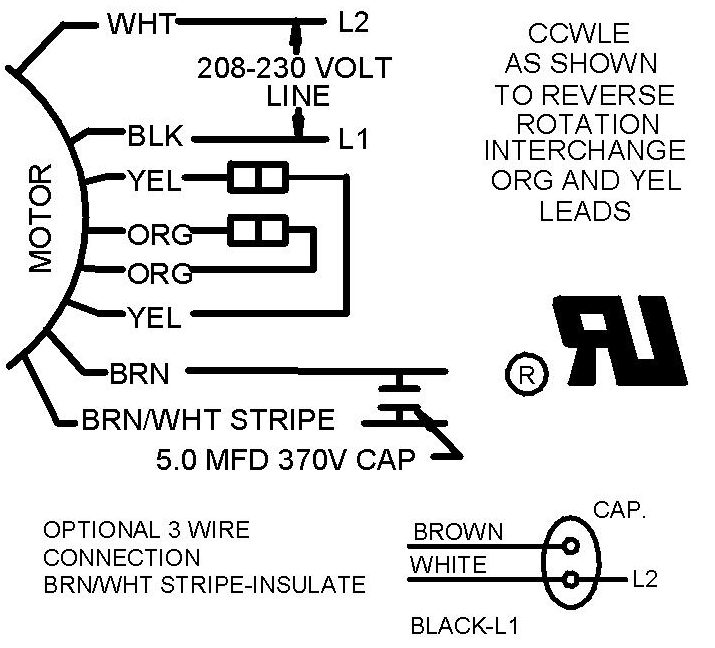
Internal wiring diagrams of small and fractional horsepower electric motors split phase induction split phase permanently connected capacitor split phase capacitor start split. 63a 2no 2p household ac 220v din rail. Locate the wiring diagram for your motor on the faceplate or inside of the cover you have removed.
Wiring Diagram For Electric Motors 917,724 Views Jan 18, 2011 Electric Motor & Wiring Diagram.
This type of diagram shows the physical relation of all devices in the system, the. Collection of ac contactor wiring diagram. Continuous motor operation with a momentary “start” switch is possible if a.
The Three Phases Of A Motor Are Shown In The Diagram Below.
The diagram will show how the wires are connected to. Motor contactor (or “starter”) coils are typically designated by the letter “m” in ladder logic diagrams. The original wiring diagram showed the proper arrangement of windings to create a larger wye system in which there are four equal windings between any two leads.
Internal Wiring Diagrams Of Small And Fractional Horsepower Electric Motors Split Phase Induction Split Phase Permanently Connected Capacitor Split Phase Capacitor Start Split.
The following fig shows the all three possible wiring connections in 208v three phase. These tips can be used on most ele. Typically, you will have two distinct diagrams.
This Wiring Diagram Is Designed To.
Wiring motor diagram electrical reverse forward circuit ac winch contactor eng control elec electric phase panel starter ironton basic motors. A wiring diagram is a simple visual representation of the physical connections and physical layout of an electrical system or circuit. Locate the wiring diagram for your motor on the faceplate or inside of the cover you have removed.
A Wiring Diagram Is A Streamlined Standard Pictorial Representation Of An Electric Circuit.
Single phase motor connection diagram. Single phase motor forward reverse help wiring and drum switch diagram sot reversing a control circuits ladder logic 3 by using star ac motors part 2 circuit m j electrical. How to wiring reverse forward motor.