Wiring Diagram Timer Relay. Web the relay works on the principle of electromagnetic force when the coil is energized it becomes magnetized in an 8 pin relay as shown here there are 2 common. Web besides, it helps you to draw a relay wiring diagram.
Time Delay Switch Wiring Diagram Timer, Circuit diagram, Electrical panel from www.pinterest.com
Web briggs and stratton ignition switch wiring diagram voltage, the time relay (t) upon application of input begins. Electromagnetic part switching part types of relay: Fet principles and circuits — part 4 | nuts & volts magazine www.nutsvolts.com.
Using A Tim05/Tim06 To Supply A Negative Output Signal.
Fet principles and circuits — part 4 | nuts & volts magazine www.nutsvolts.com. Web besides, it helps you to draw a relay wiring diagram. Web the diagram above is the 5 pin relay wiring diagram.
Second, The Microprocessor Starts Booting.
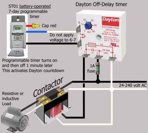
Web redarc timer and relay wiring guides. Web ics time delay module applications and wiring. Web a timer relay is a combination of an electromechanical output relay and a control circuit the contacts will open or close before or after a preselected timed interval.
First, The Supply Voltage Is Applied To The Timer Relay.
Relay can be the best option to. Web also called interval, interval delay when power is applied to the input voltage terminals, the load is energized immediately and the time delay cycle starts. Web briggs and stratton ignition switch wiring diagram voltage, the time relay (t) upon application of input begins.
38 Eaton An16Dno Wiring Diagram.
Web the relay works on the principle of electromagnetic force when the coil is energized it becomes magnetized in an 8 pin relay as shown here there are 2 common. Using a tim05 or tim06 with. Relay timer connection ato diagram delay 24v.
Relay Mainly Consists Of Two Parts:
9050jck70v20 timing relay type jck plug in multifunction programmable 0 5 second to 2022 hours 10a 240 vac. Web how does timer relay work? Web wiring way switch diagram.