Isolation Module 3 Port Wiring Diagram. First, you need to connect the negative lead of the battery to the. Web what module does my truck need?
Web 52101 harness kit 3‑port isolation module light system parts list and installation instructions a division of douglas dynamics, llc january 1, 2016. The fire wall, fender well, or radiator shroud are possible mounting locations. Web isolation module to existing brackets or harnessing.
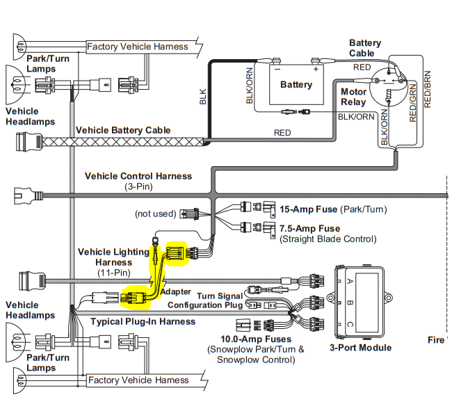
Web The Western Plow 3 Port Isolation Module Wiring Diagram Is Unique In That It Includes A “Port” Which Serves As A Junction Point Between The Various Components Of The.
This typically involves connecting each port to the main board’s power supply,. Web this is the complete truck side wiring kit for western and fisher plows. • vehicle control harness to port 1 on isolation module.* • vehicle lighting harness to port 2 on.
Web 52101 Harness Kit 3‑Port Isolation Module Light System Parts List And Installation Instructions A Division Of Douglas Dynamics, Llc January 1, 2016.
If a suitable flat surface is. Web fisher 3 port & 4 port isolation module electrical components. Web setting up the fisher plow 3 port isolation module requires careful attention to the wiring diagram.
Web The 3 Port Module Wiring Diagram Is A Comprehensive Guide That Shows How To Wire The Entire Fisher Plow System From Beginning To End.
Web the first step in port isolation module wiring is to connect all of the ports in a network. Click on the circle with number for part number & pricing. Web radiator bulkhead to the isolation module.
Reclosable Fastener Strips And/Or Cable Ties Are Supplied For Mounting The Isolation Module, But Self‑Drilling Screws Can Also Be.
The fire wall, fender well, or radiator shroud are possible mounting locations. Web what module does my truck need? First, you need to connect the negative lead of the battery to the.
Web The Vehicle For Mounting The Isolation Module (On The Driver's Side, If Possible).
And now on the fleet flex. Web isolation module to existing brackets or harnessing. Web january 23, 2023 this page contains information on the western 3 port isolation module wiring diagram, hints, and frequently asked questions.