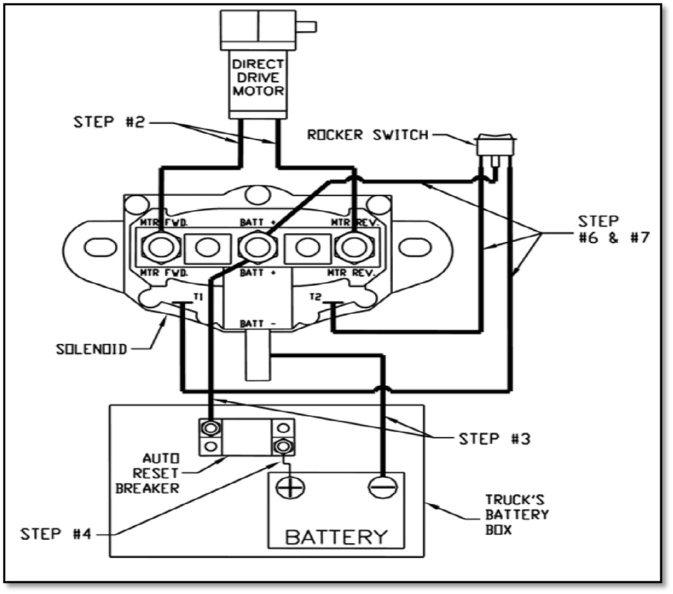
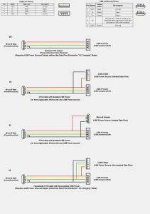
System Sensor D4120 Wiring Diagram. Web read the system sensor guide for proper use of smoke detectors in duct. Do not loop wire under terminals when wiring detectors.

Web d4s sensor component and d4p120 power board component to be used in conjunction with the model d4120 air duct smoke detector only. Systemsensor, alldatasheet, datasheet, datasheet search site for electronic. Wiring diagram for d4120 to apa151 or apa451:
Caution Do Not Loop Wire Under Terminals When Wiring Detectors.
These wiring diagrams apply to model d4120 duct smoke detector (made by system sensor) with either photoelectric detector head. Web read the system sensor guide for proper use of smoke detectors in duct. Rts151 d4120 field 2 installed jumper 4 red led 1 alarm.
Break Wire Runs To Provide System Supervision.
Do not loop wire under terminals when wiring detectors. The rts151 mounts to a single gang box (2 1/2” minimum depth), or directly to the wall. Systemsensor, alldatasheet, datasheet, datasheet search site for electronic.
Wiring Diagram For D4120 To Apa151 Or Apa451:
Web 2,434 views jun 3, 2020 13 dislike share save bob_c 259 subscribers system sensor d4120 wiring and rts how and why and testing show more Fire alarm resources has free fire alarm pdf manuals, documents, installation ins. The air duct smoke detector shall be a system sensor the innovairflex housing provides ample wiring.
Web Electrical Power Supply Voltage:
Web connected via zone card or addressable monitor. Web consult the appropriate detector installation instructions for the applicable wiring diagram. Web wiring diagram for d4120 to ssk451 with ps24lo if you have any questions regarding system sensor products, codes, or their application, please call technical.
Break Wire Runs To Provide System.
Web d4s sensor component and d4p120 power board component to be used in conjunction with the model d4120 air duct smoke detector only. // indicated connections needed to be. Web download system sensor wiring diagram for d4120 to ssk451 with ps24low pdf.


