Tachometer – MG2000 – GMALDL 14 mb Owners Manual. Three will be insu-lated and one will be uninsulated.

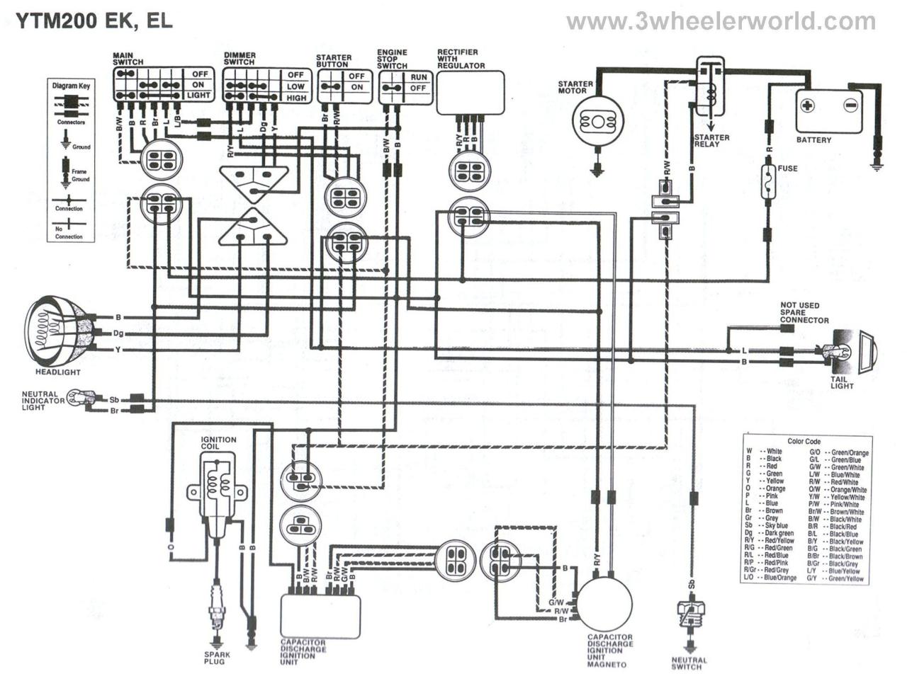
Unique Yamaha Moto 4 Wiring Diagram Yamaha Golf Carts Electric Golf Cart Diagram
Tachometer output terminal 12 cyl 6 Pulses rev 10 cyl 5 Pulses rev 8 cyl.

4 In 1 Tachometer Wiring Diagram. 4 in 1 tachometer wiring diagram. Connect the tach using the 10 shielded cable included with the tachometer. As a good starting point see step 4 Yellow wire connects to.
Mounting the Tachometer 1. Mount the tachometer corresponding to a 3 12 dia. As a good starting point see step 4 Yellow wire connects to.
4-in-1 Programmable Tachometer Process Meter Counter Zero Speed Switch. Installation images shown may be different from your actual model. Wiring Diagram arrives with a number of easy to follow Wiring Diagram Instructions.
Work with 4L 6L V6 V8 Cylinder Engines. It is intended to assist all of the average person in building a proper system. Prepare insulated ¼ spade terminals for use with the tachometer.
All in one easy to read combo package. Wiring Connect the tachometer wires as shown. Wire cutters wire strippers automotive diagnostic tool used for finding tachometer wire ratchet and sockets screwdriver drill.
1 Pulses rev. To change the PPR on tachs with three buttons follow the steps below. Wire connect the NEG terminal to a clean rustpaint-free ground preferably battery negative terminal.
Make sure all wires are long enough to reach the necessary positive and negative terminals and any wires from the sensor. Continue to use tie wraps to secure the tachometers wires to the outside of the engine compartment and up to the battery junction box. I am trying to run a IG- IG will be Ignitor and thus for the tacho.
Field programmable digital tachometer for shaft speed as low as 1 RPM microprocessor based. Usb 2 0 has a maximum signaling rate of 480 mbit s and usb 3 0 has a usable data rate of up to 4 gbit s 500 mb s. Connect the wire from the ignition coil.
Tachometer – Commander – Suzuki 2 mb Owners Manual. Fans headers and other engine hazards. Diagram j wiring from the tachometer to the ignition coil or msd 6 described on page 4 in the text and in diagram g.
Hole on the dashboard. For Chrysler Blue Gold and Silver Boxes Ford Standard Electronic ignitions and most other OEM Standard CD and Electronic ignitions. A switched 12 or 24 volt wire can.
This is the circuit diagram of Digital Tachometer Digital RPM Meter which can be used for cars or motorcycles with 2 and 4 stroke petrol engines with any number of cylinders and contact. To avoid cutting or unsheathing the wire use a rubber grommet when passing them through a firewall or sheetmetal. Wire connect the POS terminal to a switched 12V source like the ignition wire.
Connect the tachometer wires as shown in the wiring diagrams below which are typical installations 4. Make sure your tach is set up for your engines cylinder count. Operating range 500 to 30000 input pulses per minute.
The wiring diagram shown is a typical installation. Coil trigger wire some cars. Peel approximately 3 to 4 inches of the outside covering and aluminum shielding from the gray cable.
Tachometer guage wiring diagram for 4g63t tachometer guage wiring diagram for 4g63t external Autogauage – Mitsubishi 1996 Eclipse question. A secure ground connection will help the tachometer to run correctly. This will reveal four individual wires.
Mine was salvaged from my old truck 3M quick splice connectors 14-18 gauge – – – – – 410 Walmart Tools. Otherwise the arrangement will not work as it ought to be. The tachometer is configured at the factory for 4 PPR.
Tach Wiring Diagram dixco tach wiring diagram harley tach wiring diagram pro tach wiring diagram Every electric arrangement is composed of various distinct pieces. Jdm Tachometer Wiring Diagram Brand new. Tachometer wiring excerpt of 123GT diagram 1800 tach wiring is substantially the same.
Connect the tachometers black wire to the battery ground of the vehicle. Faceplate gasket kit gives a NEMA 4X rating when installed in similarly rated. I have a 5 4 in 1 tach from AT racing world.
Connect the green wire to the negative post of an existing. 12 Pulses rev. Disconnect negative – battery cable.
Negative side of coil some cars or coil control wire some cars or coil trigger wire some cars. Tachometer – – – – – Can be purchased from most any auto parts store for as low as 33. Speedometer – MG3000 – NMEA2000 J1939.
JDM Instrument Cluster Wiring Diagram – posted in A80 MKIV Discussion. Insert the tachometer into the bracket and secure it by using the screws and lock washers provided. 3 TACHOMETER WIRING Figure 2.
Installation instructions 5 tachometer 2650 1244 00 rev. Youll often see an internal switch for 4- 6- or 8-cylinders. Depth Sounder – Dual AirWater Temperature.
18 DIN housing 12 digital display. Align it so that the tachometer is straight when viewed from the drivers position. Dont have cant find a wiring diagram for it plus ive never done anything like this.
12V BATTERY COIL Ignition Coil Tach base can be mounted in either direction for convenient mounting. Each component ought to be placed and connected with other parts in particular manner. Usb Keyboard Wiring In 2020 Color Coding Electronic Schematics Electronics Projects Diy.
Im not trying to hook up the water temp or any of that just rpms. Connect the wire from the light switch to the remaining terminal on the lamp socket. Wire cutters Wire strippers Automotive diagnostic tool-used for finding tachometer wire Ratchet and sockets Screwdriver Drill.
WHITE RED BLACK GREEN. 356 Tach Wiring Wiring Diagram Tachometer Wiring Diagram. With no power applied to the tach press and hold the SET button.
Connect the wire from pin 4 to a switched 12 volt or 24 volt source. Be sure to wire the tachometer before mounting. Wiring configuration is different than most Tachometers20150213 200330.
Diagram I Wiring to MSD-7AL Ignition 2. JDM Style 5 4in1 LED Tachometer Super White Glow Gauge. 1 3 4 1 8 Note.
Auto Meter gave us some other tach-installation tips too. Connect the tachometer wires as shown in the wiring section.

Yc 5002 Yamaha Yfm350 Wiring Diagram Free Diagram Yamaha V Star Yamaha Diagram

Wire Harness Wiring Cdi Assembly For 50 70 90 110cc 125cc Atv Quad Coolster Go Kart Wish In 2022 Motorcycle Wiring 90cc Atv Chinese Scooters

Wiring Diagram For 110cc 4 Wheeler Fresh 110 Atv Wiring Help Atv Electrical Diagram 150cc Chinese Scooters

Craftsman Riding Mower Electrical Diagram Wiring Diagram Craftsman Riding Lawn Mower I Need One For Craftsman Riding Lawn Mower Lawn Mower Riding Mower

Lewmar Windlass Wiring Diagram Upgrade Windlass Power Wiring Of Lewmar Windlass Wiring Diagram With Windlass Wiring Diagram For Windlas Diagram Power Wire Wire

Unique Wiring Diagram For Chinese 110cc Atv Wiring Diagram Chinese Atv Wiring Diagrams Roketa 11 Motorcycle Wiring Electrical Diagram Electrical Wiring Diagram

Wiring Diagram For 110cc 4 Wheeler Rate Chinese 110cc Atv Wiring Electrical Diagram 90cc Atv Atv

Dolphin Gauges Wiring Diagram Best Of Diagram Solar Energy Diy Wire

Honda Xl100 Motorcycle Complete Wiring Diagram All About Wiring Diagrams Electrical Wiring Diagram Motorcycle Paint Jobs Honda

110cc Chinese Atv Wiring Diagram Schaferforcongressfo Motorcycle Wiring Pit Bike Trailer Wiring Diagram

Installation Of Single Pole 3 Way 4 Way Switches Wiring Diagram Electrical Wiring Home Electrical Wiring Electrical Switch Wiring

30 Beautiful Freightliner Starter Wiring Diagram Willys Jeep Freightliner Jeep Cj7

30 Lovely Peterbilt Starter Wiring Diagram Electrical Wiring Diagram Electrical Diagram Automotive Electrical

Unique Trane Heat Pump Thermostat Wiring Diagram Thermostat Wiring Electrical Diagram Trane Heat Pump

Diagram Electric Furnace Electrical Circuit Diagram

18 Motorcycle 4 Wire Ignition Switch Diagram Motorcycle Diagram Wiringg Net Motorcycle Wiring Electrical Diagram Electrical Wiring Diagram

Nordyne Hvac Wiring Diagrams Schematics In Furnace Diagram In E2eb 015ha Wiring Diagram Electric Furnace Furnace Gas Furnace

On Free Wiring Diagrams Motorcycle Wiring Diagram Electrical Wiring Diagram


