With all the help of this book you are able to easily do your own wiring assignments. One end of the adapter plugs into the car stereo the other end plugs into the wiring harness that originally connected to the factory stereo and that s all there is to it.
Pioneer Car Audio Wiring Diagram Pioneer Car Audio Pioneer Car Stereo Car Audio
I need a wiring diagram for a pioneer deh xbt.

Wiring harness pioneer car stereo wiring diagram. I have the radio and a wiring harness on order for my honda s i downloaded. Our extensive car stereo wiring harness collection ensures that you will find the exact wire harness connector kit needed for you car. Here is a picture gallery about pioneer car stereo wiring diagram free complete with the description of the image please find the image you need.
Car radio wire diagram stereo wiring diagram gm radio wiring diagram. Pioneer car radio stereo audio wiring diagram autoradio connector wire installation schematic schema esquema de conexiones stecker konektor connecteur cable shema car stereo harness wire speaker pinout connectors power how to install. Pioneer car radio wiring diagrams.
Pioneer radio wiring diagram colors collections of car stereo wiring diagram subaru valid wiring diagram color. Variety of pioneer stereo wiring diagram. A wiring diagram is a streamlined traditional pictorial representation of an electric circuit.
Pioneer wiring schematic pioneer wiring schematic wiring diagrams pertaining to pioneer car stereo wiring diagram free image size 500 x 319 px and to view image details please click the image. All wiring has electronic industries association. You ll be able to usually depend on wiring diagram as an important reference that will assist you to preserve money and time.
Scosche wire harness kits are the best in the industry and ensure an easy and clean car stereo installation. Car wiring diagram colours 2019 lovely wiring diagram color codes. Plugs into the 4 specific pioneer radio s and has 8 color coded leads.
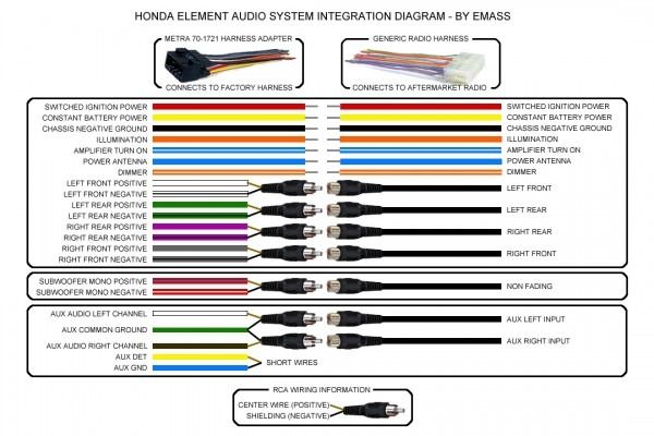
Learn about the wire harness color codes for pioneer 2016 avh x models with video screens. 2003 jaguar s type radio wiring diagram best ponent cables car. It shows the elements of the circuit as streamlined forms as well as the power as well as signal connections between the gadgets.
If you can get your hands on the right car stereo wiring adapter it vastly simplifies the installation process. Wiring diagram kenwood top rated car audio wiring diagrams lovely. Pioneer car stereo wiring harness diagram wiring diagrams hubs pioneer wiring diagram.
You can find more information about the dimmer settings here https.

Wiring Diagram Car Radio Bookingritzcarlton Info Pioneer Car Stereo Color Coding Color

Dual Stereo Wiring Diagram 1 Car Amp Pioneer Car Stereo Car Audio

Wiring Diagram Pioneer Car Stereo Wiring Diagram Free Pioneer Pioneer Car Audio Pioneer Car Stereo Car Audio

Double Din Wiring Harness 25 Wiring Diagram Images Wiring Diagrams Crackthecode Co Jdm Pioneer Car Stereo Kit

Stereo Wiring Harness Diagram Pioneer Car Stereo Car Stereo Avh

Wiring Diagram Car Radio Bookingritzcarlton Info Kenwood Car Audio Car Audio Pioneer Radio

Wiring Diagram Car Radio Http Bookingritzcarlton Info Wiring Diagram Car Radio Sony Car Stereo Pioneer Car Stereo Pioneer Car Audio
Car Stereo Wiring Harness Diagram Sony Car Stereo Kenwood Car Subwoofer Wiring

Electrical Wiring Aftermarket Stereo Wiring Diagram Jvc Radio Wire Harness 81 Jvc Radio Wire Harness 81 Wiring Sony Car Stereo Kenwood Car Subwoofer Wiring

Pioneer Avh P3100dvd Wiring Diagram Pioneer Car Stereo Pioneer Car Audio Car Stereo

Car Stereo Wiring Diagrams Free Pioneer Car Stereo Sony Car Stereo Car Stereo

Credit Image Http Www Seicane Com Mitsubishi Car Radio Stereo Audio Wiring Diagram Autoradio In 2020 Car Stereo Diy Car Audio Systems Diy Car Audio Installation

Kenwood Kdc 138 Wiring Diagram Pioneer Car Stereo Car Stereo Electrical Wiring Diagram

Unique Typical Car Stereo Wiring Diagram Diagram Diagramtemplate Diagramsample Elektronica Muziek

17 Pioneer Car Stereo Wiring Diagram Deh P3100 Car Diagram Wiringg Net In 2020 Pioneer Car Stereo Sony Car Stereo Car Stereo

Car Stereo Wiring Harnesses Interfaces Explained What Do The Unusual Wire Diagram Pioneer Car Stereo Car Stereo Car Stereo Systems

Pioneer Car Audio Wiring Diagram And Alpine Wiring Harness Color Code Getting Started Of Wiring In 2020 Pioneer Car Audio Car Audio Sony Car Stereo

Kenwood Stereo Wiring Diagram Color Code Wire Harness Colors Radio With Beautiful Jvc Car Within Audio 1 Kenwood Stereo Pioneer Radio Electrical Wiring Colours

Pioneer Radio Wiring Diagram Pioneer Car Stereo Pioneer Radio Car Stereo