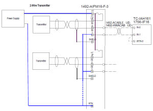
1492 Ifm40F Wiring Diagram. Pinout diagram using cable**n3 with ib32 input module. (reference connector and crimp type pins for connection to i/o wiring.
Find all available product literature for this product in the literature library results. Aufklebbare etiketten zur kennzeichnung der. Fuses (5 x 20 mm) are not.
Find All Available Product Literature For This Product In The Literature Library Results.
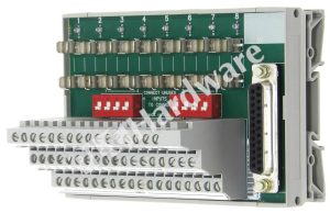
Web 1492 wiring systems modules, digital module with fixed terminal block, 40 pins, led indicating, sensor, 24v ac/dc, two per i/o connection Web 1492 wiring systems modules, digital module with fixed terminal block, 40 pins, fusible, 120v ac, isolated extra terminal w/ blown fuse indicator for outputs, four per i/o. Fusing — fuse holders are.
(Reference Connector And Crimp Type Pins For Connection To I/O Wiring.
Aufklebbare etiketten zur kennzeichnung der. Fusing — fuse holders are included with the ifm. Download this pdf document to learn about its features, specifications, dimensions, and wiring.
Wiring — Refer To The Label Section.
Pinout diagram using cable**n3 with ib32 input module. Wiring — refer to the label section on page 174. Digital module with fixed terminal block:
Web 1492 Wiring Systems Modules, Digital Module With Fixed Terminal Block, 40 Pins, Fusible, Sensor, 120V Ac, Two Per I/O Connection.
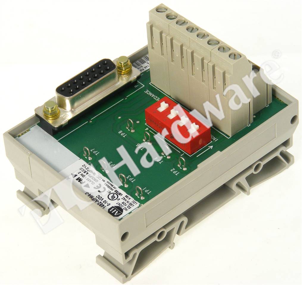
Compatibility — to ensure proper operation with the i/o module, do not exceed the voltage and current ratings of the ifm. Fuses (5 x 20 mm) are not. Web 1 adhesive label card.
Identifie Le Câblage Des Bornes.
Digital module with fixed terminal block: