1794 Tbnf Wiring Diagram. Flex i/o terminal base units. Allow 25.4 mm (1 in.) of space between adjacent equipment for adequate ventilation.
Connect wiring for the 1794tbn Rockwell Automation 1794IF4I FLEX I from www.manualsdir.com
Allow 25.4 mm (1 in.) of space between adjacent equipment for adequate ventilation. Flex i/o 240v ac digital input and. Learn how to avoid the risks of.
Select A Flex I/O Terminal Base Unit.
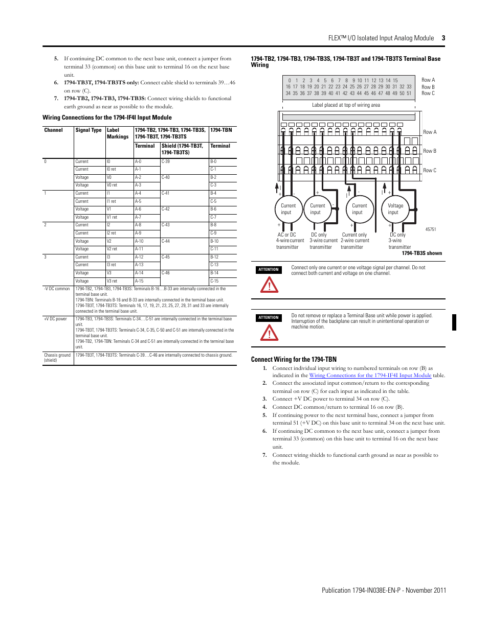
Connect individual input wiring to the even numbered terminals on row (b) as indicated in the table below. Connect individual output relay contact (customer load) to even numbered terminals (0 thru 14) on row (b) and odd. Web the examples and diagrams in this manual are included solely for illustrative purposes.
Web Wiring To A 1794Tbn Or Tbnf T Erminal Base Unit 1.
The flextm i/o relay output module mounts on a 1794 terminal base. The appropriate terminal base unit for your module and. Flex i/o 240v ac digital input and.
Learn How To Avoid The Risks Of.
Allow 25.4 mm (1 in.) of space between adjacent equipment for adequate ventilation. Web connect wiring for analog inputs and outputs 1. Learn how to avoid the risks of unauthorized and counterfeit products.
Flex I/O Terminal Base Units.
Flex i/o 8 analog input. Learn how to avoid the risks of. Web the flextm i/o ac digital output module mounts on a 1794 terminal base.