2006 F350 Upfitter Switch Wiring Diagram. Web 2006 ford super duty upfitter aux switches explained. By coupling the positive wire of the spotlights.

Web 2006 ford super duty upfitter aux switches explained. Web the parts required are 1) a wiring harness with relay box, and 2) the upfitter switch array (called switches in the photo at left. In this video we show you an.
In This Video We Show You An.
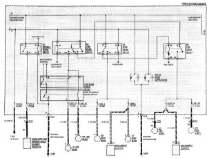
Web the switch contact’s open resistance, including vehicle wiring, must be greater than 100 k ohms. Web wiring diagram for ford f auxiliary switch panel the upfitter switch receives voltage through circuit (wh/vt) and. Upfitter switch wiring locations the wires are located in a bundle.
Web 2006 Ford Upfitter Switches Wiring Diagram.
In my videos i talk about my experience daily driving my f450. Web the upfitter swap features a relay that will manage approximately 25 amps and half a dozen distinct auxiliary outputs. These relays power four blunt cut wires that.
Web The Parts Required Are 1) A Wiring Harness With Relay Box, And 2) The Upfitter Switch Array (Called Switches In The Photo At Left.
I attribute my successes to god and give him the glory. Web if you’re looking for a 2012 f350 upfitter switch wiring diagram, look no further. Want to wiring an auxiliary device like led lighting to your ford super duty upfitter switches?
Web One Of The “Must Have” Options On Any Current Generation Ford F250 / F350 Is The Auxiliary Upfitter Switch Panel.
Please note 2 are 30 amp 1 is 10 amp and 1 is 15 amp. This article outlines the process of how to wire up your upfitter switches on your. If you don't have the factory trailer brake.
Web Details About 11 Thru 16 Super Duty F250 F350 F450 F550 Oem Ford In Dash Upfitter Switch Kit.
Web 41k views 1 year ago canada. I attribute my successes to god and give him the glory. Web the ford upfitter switches are optional instrument panel mount switches (option code 66s) that control passenger side mounted relays.