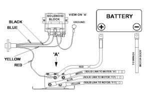
3-Wire Cam Sensor Wiring Diagram. Wiring diagram for 3 wire crankshaft sensor. Two power wires and one load wire.
Crank Sensor Wiring Diagram Wiring Diagram and Schematic from wiring.hpricorpcom.com
2 wire is mag impulse and uses no power, it creates its' own. Hot power wire (5 volt reference voltage comes from the. 3 wire proximity sensor wiring diagram.
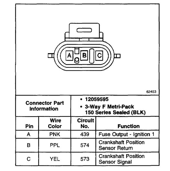
The Resistance Readings Should Be As Follows:
This step isolates the sensor for easier troubleshooting. The 3 wire crank sensor has three wires mentioned below. How to remove or swap the rns510, rns315, or rcd510 radio or gps.
All Wallpapers And Backgrounds Observed Here Are Believed To Get Within The Public Domain.
2 wire is mag impulse and uses no power, it creates its' own. Hot power wire (5 volt reference voltage comes from the. In depth oem wiring diagrams.
3 Wire Proximity Sensor Wiring Diagram.
3 wire is power, ground and. Hot power wire (reference voltage comes from the ecu) ground wire signal wire. All three wires connect to the ecu.
The Load Is A Device.
The wiring diagram of the coolant temperature sensor is based on year make and model. I have cut just the bit you need below. Underneath is the entire tutorial.
The Power Wires Will Connect To A Power Supply And The Remaining Wire To Some Type Of Load.
An easy way to remember pnp and npn sensor wiring automation insights fc spx200 series small u shape photo sensors switches fiber optical what is the difference between when describing 3. 3 wire is hall effect and uses external power. Connect the black multimeter test lead to the wire labeled with the letter “b” always check that you are probing the correct.