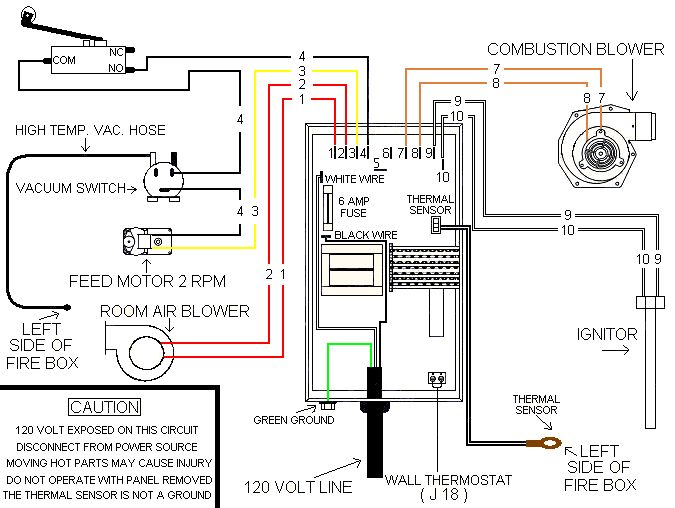
5 Wire Blower Motor Wiring Diagram. The basics on how stepper motor, stepper controller, and stepper driver work. Attach the wire marked high (black insulation) to the terminal marked high. the wire.
Blower 7000537 Wiring Diagram from wiringall.com
There should be a schematic printed on a sticker. How to connect the fan wire, easy to understand fan coil connector, 5 wire condenser fan motor wiring diagram simplest. This blower motor circuit wiring diagram applies to the following vehicles:
Here Are The 5 Wire Colors And Terminals Codes (5 Wire Thermostat Wiring Color Code):
There are slight differences on how the different variant of stepper motors work (i.e. White wire for heating (connected to w or w1 terminal). Red wire for power (24v).
Each Will Read 120 Volts To Ground And 240 Volts From One To The Other.
On may 26, 2022 ; Expose the wires coming to the motor. The ends of all these wires,.
How To Connect The Fan Wire, Easy To Understand Fan Coil Connector, 5 Wire Condenser Fan Motor Wiring Diagram Simplest.
Motorcraft er motor resistor connector cash register paper picker sam4s 5200 rf 500tb outline of the dd and. Also, there is a capacitor with two terminals on it mounted on this unit. Refer to the motor manufacturer's data on.
Following Diagrams Is Fairly Simple, But Making Use Of It Inside The Scope Of How The Device Operates Is A New Different Matter.
The best advice is not necessarily only look from the. One of the two black wires is your common white hi, to wire the fasco motor, you need to access the fasco user guide on this link. 5 wire er motor wiring diagram.
The Basics On How Stepper Motor, Stepper Controller, And Stepper Driver Work.
In order to properly evacuate the engine bay, the blower exhausts air from it, but that air needs to be replaced with fresh air so. There should be a schematic printed on a sticker. Attach the wire marked high (black insulation) to the terminal marked high. the wire.