Source: stillwriting-clarissa.blogspot.com
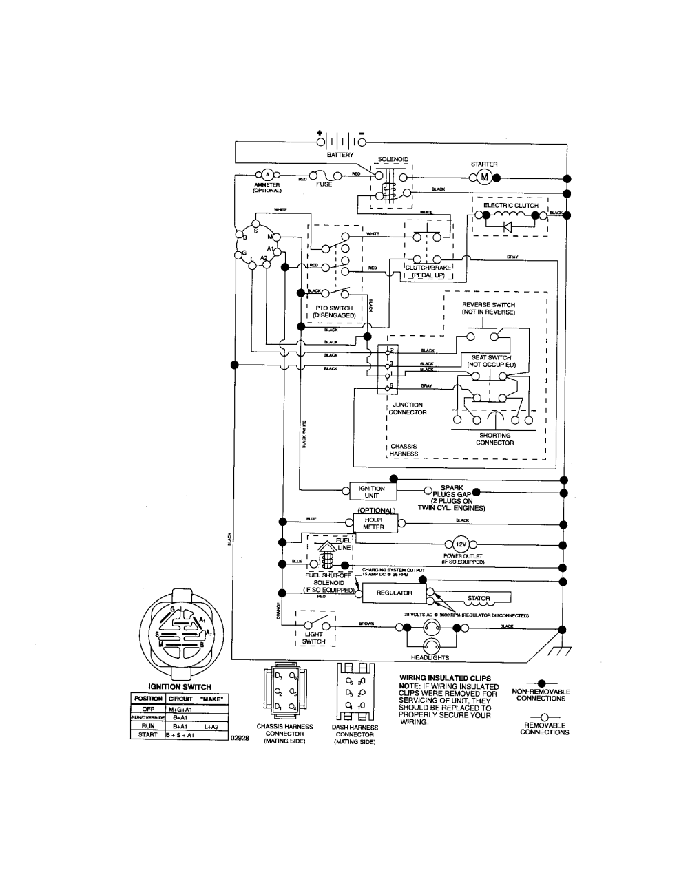
Web 6 prong ignition switch wiring diagram: Each accessory has a single terminal labeled “l” or “y.” however, the labeling depends.
Source: www.pontoonboatforum.com
Each accessory has a single terminal labeled “l” or “y.” however, the labeling depends. Step 7 connect the accessories.
Source: 2020cadillac.com
Web 6 prong ignition switch wiring diagram: Web grey socket grey 7 core wiring pin 1 yellow, reverse pin 2 blue, supplementary feed (ignition) pin 3 white, earth pin 4 green live feed (battery +) pin 5 brown not.
Source: www.justanswer.com
Web grey socket grey 7 core wiring pin 1 yellow, reverse pin 2 blue, supplementary feed (ignition) pin 3 white, earth pin 4 green live feed (battery +) pin 5 brown not. Web 6 prong ignition switch wiring diagram:
Source: headcontrolsystem.com
Web 6 prong ignition switch wiring diagram: Web grey socket grey 7 core wiring pin 1 yellow, reverse pin 2 blue, supplementary feed (ignition) pin 3 white, earth pin 4 green live feed (battery +) pin 5 brown not.
Source: wiringall.com
Each accessory has a single terminal labeled “l” or “y.” however, the labeling depends. Web grey socket grey 7 core wiring pin 1 yellow, reverse pin 2 blue, supplementary feed (ignition) pin 3 white, earth pin 4 green live feed (battery +) pin 5 brown not.
Source: www.pinterest.com
Web grey socket grey 7 core wiring pin 1 yellow, reverse pin 2 blue, supplementary feed (ignition) pin 3 white, earth pin 4 green live feed (battery +) pin 5 brown not. Each accessory has a single terminal labeled “l” or “y.” however, the labeling depends.
Source: wiringall.com
Step 7 connect the accessories. Web grey socket grey 7 core wiring pin 1 yellow, reverse pin 2 blue, supplementary feed (ignition) pin 3 white, earth pin 4 green live feed (battery +) pin 5 brown not.
Source: hestiahelper.blogspot.com
Web 6 prong ignition switch wiring diagram: Each accessory has a single terminal labeled “l” or “y.” however, the labeling depends.
Source: www.pinterest.com
Step 7 connect the accessories. Web grey socket grey 7 core wiring pin 1 yellow, reverse pin 2 blue, supplementary feed (ignition) pin 3 white, earth pin 4 green live feed (battery +) pin 5 brown not.
Source: www.fixya.com
Each accessory has a single terminal labeled “l” or “y.” however, the labeling depends. Step 7 connect the accessories.
Source: wiringdiagrams3.blogspot.com
Web grey socket grey 7 core wiring pin 1 yellow, reverse pin 2 blue, supplementary feed (ignition) pin 3 white, earth pin 4 green live feed (battery +) pin 5 brown not. Step 7 connect the accessories.
Source: headcontrolsystem.com
Each accessory has a single terminal labeled “l” or “y.” however, the labeling depends. Web 6 prong ignition switch wiring diagram:
Source: diysweep.blogspot.com
Each accessory has a single terminal labeled “l” or “y.” however, the labeling depends. Web 6 prong ignition switch wiring diagram:
Source: inspireoont.blogspot.com
Each accessory has a single terminal labeled “l” or “y.” however, the labeling depends. Step 7 connect the accessories.
Source: www.dentistmitcham.com
Web grey socket grey 7 core wiring pin 1 yellow, reverse pin 2 blue, supplementary feed (ignition) pin 3 white, earth pin 4 green live feed (battery +) pin 5 brown not. Each accessory has a single terminal labeled “l” or “y.” however, the labeling depends.
Source: asicskinsei3fast.blogspot.com
Each accessory has a single terminal labeled “l” or “y.” however, the labeling depends. Web 6 prong ignition switch wiring diagram:
Source: homewiringdiagram.blogspot.com
Each accessory has a single terminal labeled “l” or “y.” however, the labeling depends. Step 7 connect the accessories.
Source: 2020cadillac.com
Web grey socket grey 7 core wiring pin 1 yellow, reverse pin 2 blue, supplementary feed (ignition) pin 3 white, earth pin 4 green live feed (battery +) pin 5 brown not. Web 6 prong ignition switch wiring diagram:
Source: schematicschematicmark.z21.web.core.windows.net
Each accessory has a single terminal labeled “l” or “y.” however, the labeling depends. Web grey socket grey 7 core wiring pin 1 yellow, reverse pin 2 blue, supplementary feed (ignition) pin 3 white, earth pin 4 green live feed (battery +) pin 5 brown not.
Source: trailer-wiring-diagram.com
Step 7 connect the accessories. Web grey socket grey 7 core wiring pin 1 yellow, reverse pin 2 blue, supplementary feed (ignition) pin 3 white, earth pin 4 green live feed (battery +) pin 5 brown not.
Source: www.infinitybox.com
Step 7 connect the accessories. Each accessory has a single terminal labeled “l” or “y.” however, the labeling depends.
Source: www.pinterest.com
Web grey socket grey 7 core wiring pin 1 yellow, reverse pin 2 blue, supplementary feed (ignition) pin 3 white, earth pin 4 green live feed (battery +) pin 5 brown not. Web 6 prong ignition switch wiring diagram:
Source: headcontrolsystem.com
Each accessory has a single terminal labeled “l” or “y.” however, the labeling depends. Web grey socket grey 7 core wiring pin 1 yellow, reverse pin 2 blue, supplementary feed (ignition) pin 3 white, earth pin 4 green live feed (battery +) pin 5 brown not.
Source: wiring05.blogspot.com
Web grey socket grey 7 core wiring pin 1 yellow, reverse pin 2 blue, supplementary feed (ignition) pin 3 white, earth pin 4 green live feed (battery +) pin 5 brown not. Web 6 prong ignition switch wiring diagram:
Source: diagramweb.net
Web 6 prong ignition switch wiring diagram: Web grey socket grey 7 core wiring pin 1 yellow, reverse pin 2 blue, supplementary feed (ignition) pin 3 white, earth pin 4 green live feed (battery +) pin 5 brown not.