Balanced To Unbalanced Wiring Diagram. A balanced audio signal works with three wires. Some connectors are red, some black and some are yellow.
Amazon.in Professional Audio Buying Guide Musical Instruments from www.amazon.in
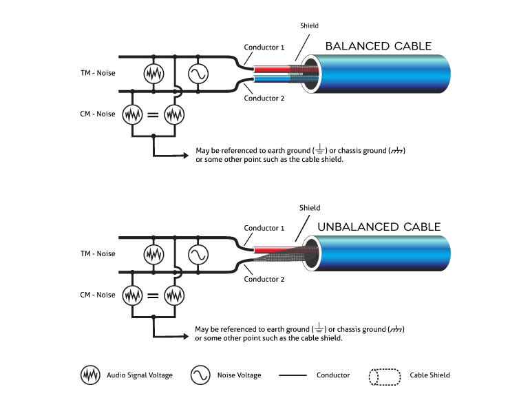
Balanced connections are “professional,” unbalanced connections are characteristic of consumer or “prosumer” gear. This connects the xlr pin 3 to ground, thereby effectively transforming the console's xlr out to an unbalanced output. Use 3 resistors in the xlr's then the remaining two of each in.
As mentioned before, it takes two wires to make a lane for data. Some connectors are red, some black and some are yellow. Cable soldering schematics how to white noise studio wiring audio inputs and outputs biamp cornerstone dealing with unbalanced gear in the crookwood neutrik nc3fxs b.
Most Unbalanced Signals Travel Coax Cables But A Few Do Not.
A balanced audio signal works with three wires. This was close to true in the early days of the project studio. If you have red and white connectors, the red is the right channel and the.
It's Up To You Guys To Solder The Wires, Connectors, And Assemble The Chassis.
The quickest, easiest and 'dirtiest' diy approach would be to cut off the ts plugs from the interface end of your existing unbalanced cables, and solder on new trs plugs for the. The cable connection balanced and unbalanced electrical wiring majorcom dealing with unbalanced gear in the studio crookwood psr 970 output connections. Wiring unbalanced to balanced with transformer.
Xlr To Ts Is The Correct Cable.
Balanced vs unbalanced audio connections difference explained. Rj 45 to balanced or unbalanced audio cable wiring teloshelp. Xlr to 1/4 balanced wiring diagram from schematron.org.
In this configuration, the sleeve of the output. Balanced cables have three conductors while unbalanced ones have fewer, and. Balanced connections are “professional,” unbalanced connections are characteristic of consumer or “prosumer” gear.