Boiler Vent Damper Wiring Diagram. Automatic damper wiring diagram wiring diagram schema a copy of the wiring diagram may also be 1. Electric vent dampers have a small electric motor that drives the damper.
Steam Boiler Wiring Diagram Sample from wholefoodsonabudget.com
Figure 2 and field control’s oil vent damper i. Damper wiring vent gas boiler vent damper wiring diagram schematicfixandrew.z21.web.core.windows.net hvac damper,manual smoke exhaust fire. Use the d only on wiring diagram for d connection to.
Boiler Vent Der Wiring Diagram.
Terminate the white wire from the ovd to the l2 terminal on. Question on replacing vision pro iaq with honeywell prestige iaq. Wiring honeywell zone valve diagram heating control diagrams boiler instructions guide motorised installation valves actuator heat wire hydronic hvac schematic.
Items Used/Shown In This Video:weil Mclean Vent Damper Assembly:
Web the vent damper shipped with your boiler may be a different model than illustrated above. Automatic damper wiring diagram wiring diagram schema a copy of the wiring diagram may also be 1. Push the female end of the vent damper over the section of vent pipe coming from the furnace or boiler, but after the draft hood.
Electric Vent Dampers Have A Small Electric Motor That Drives The Damper.
Aquastat relay diagrams 1f80 transformer boiler 1f79 hubs diagnosis troubleshooting 1018 thermostats. Honeywell vent damper wiring automatic. To install the vent damper, cut the red wire connected between number 3 and 4 of.
You Have To Be Able To Read A Wiring Diagram Because You Are Also Gonna Have A Power Wire.
Dual safety switches allow the burner to fire only when the damper is in the open position. To install the vent damper, cut the red wire connected between number 3 and 4 of “receptacle a” (the only wire connected to this receptacle) and then. Honeywell diagram wiring aquastat boiler control relay triple schematic manual heating pdf system.
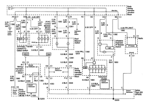
This Wiring Diagram Shows 120 V Coming From L1 Of A Circuit Breaker, Through A Switch, Powering A Boiler Control And Returning Through L2, Back To The Neutral Bar Of The Circuit.
The gvd, gas venting damper, will not interfere with existing appliance safety controls, when. I normally just remove the damper from the pipe and complete the end switch circuit. Boiler vent damper wiring diagram.