Boss Rt3 V Plow Wiring Diagram. Drag pro 180z manifold diagram. Power v dxt harness wiring parts for straight blade rt3 diagram sport duty boss plow lights won t turn off snow side 11pin to 13pin 61791 western or 7948 fisher hb5 new.
Boss Rt3 V Plow Wiring Diagram Collection from www.got2bwireless.com
Cant seem to find the electrical wiring diagram. Boss control kit smarttouch 2 rt3 straight plow stb15103. Boss plow wiring schematic free wiring diagram.
Boss Snow Plow Rt3 Wiring Diagram.
Wiring schematic wiring schematic g10004. Boss ldr box plow diagram. Boss plow wiring schematic free wiring diagram.
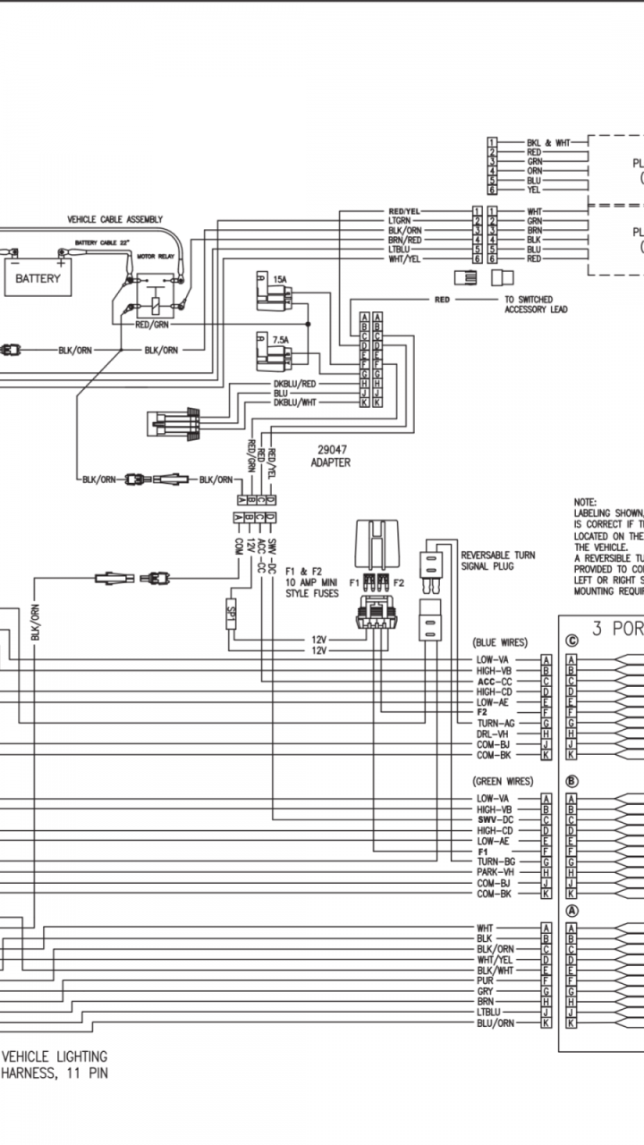
Cant Seem To Find The Electrical Wiring Diagram.
When plowing on a solid level area (parking lots, roads, and driveways) plow shoes can be raised up to increase cutting edge contact on the plowed surface. Refer to the manifold wiring diagram in this manual. Drag pro and 180z vehicle side.
New Snow Plow Motor Control Solenoid Hyd01633 Rt3 Rt2 For Boss Snowplow Image By Www.ebay.com Replacement Push Frame.
That being said, we are not rebuilding and putting back together. Boss rt3 v plow wiring diagram effectively read a cabling diagram, one provides to find out how the components inside the program operate. Web please download these boss v plow wiring diagram.
Insert The Unconnected Ends Of The Plow Wiring Harness Into The Back Of The Coupler Through The Rubber Grommet.
Rt3 wing not functioning | the. 25 aug, 2021 post a comment msc04317 home home gt boss rt3 wiring harness 13 pin boss rt3 wiring harness 13 pin serial is less than h3732 lt lt go back to v blade parts lt lt go back to. Western vehicle side wiring diagram 3 port plug rt3 tripedge snowplow western snow plow unimount straight blade hydraulic parts receiver solenoid box details.
Rt3 Wiring Diagram Rt3 Wiring Diagram.
Find the besttemplates at champion. Check for voltage between solenoid valve terminal and ground with ignition switch on and control switch in float position. Plow boss diagram controller hand parts circut held.