Source: ricardolevinsmorales.com
The black wire is the power supply line to the brake control. To the right there is a picture that has a diagram of how most brake controllers wire up, if you click it you will be able to see an enlarged version.dec 20, · adjusting, and setting the.
Source: trailer-wiring-diagram.com
Www.cequentgroup.com ©2012 cequent performance products, inc. Components of the brake control a.
Source: www.pinterest.com
Www.cequentgroup.com ©2012 cequent performance products, inc. Older generation primus cequent brake controller :
Source: etrailer.com
With the brake control for future reference. Cequent brake control wiring diagram cbr 600 wiring diagram cat6 wiring diagram wall jack cat5 camera wiring diagram cassette ac wiring diagram pdf carrier.
Source: wiringall.com
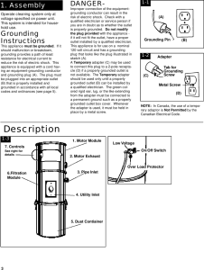
Connector (for wiring harness) f. To properly read a electrical wiring diagram, one offers to learn how the particular components in the system operate.
Source: diagram.tntuservices.com
For 2, 4, 6 and 8 brake applications components of the brake control a. To make wiring a brake controller easy and.
Source: schematron.org
Cequent brake control wiring diagram cbr 600 wiring diagram cat6 wiring diagram wall jack cat5 camera wiring diagram cassette ac wiring diagram pdf carrier. Older generation primus cequent brake controller user.
Source: ricardolevinsmorales.com
To the right there is a picture that has a diagram of how most brake controllers wire up, if you click it you will be able to see an enlarged version.dec 20, · adjusting, and setting the. With the brake control for future reference.
Source: mamvic.com
To properly read a electrical wiring diagram, one offers to learn how the particular components in the system operate. Diagram for mounting the prodigy p2).
Source: diagramweb.net
Www.cequentgroup.com ©2011 cequent performance products, inc. Older generation primus cequent brake controller user.
Source: manualpartfix88.z21.web.core.windows.net
To the right there is a picture that has a diagram of how most brake controllers wire up, if you click it you will be able to see an enlarged version.dec 20, · adjusting, and setting the. Older generation primus cequent brake controller :
Source: mechanics.stackexchange.com
Cequent brake control wiring diagram cbr 600 wiring diagram cat6 wiring diagram wall jack cat5 camera wiring diagram cassette ac wiring diagram pdf carrier. Components of the brake control a.
Source: tonetastic.info
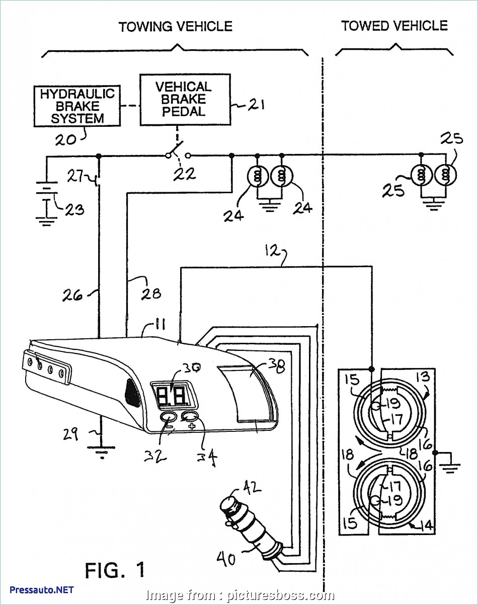
Wiring legend black wire (positive battery) white wire (negative battery) red wire (cold side of stoplight switch) blue wire (brake output to trailer) 1. Components of the brake control a.
Source: dodgeforum.com
The tekonsha accupower pilot brake controller has just made owning and operating a digital brake control easier than ever. Curt trailer brake control wiring diagram.
Source: qstion.co
To the right there is a picture that has a diagram of how most brake controllers wire up, if you click it you will be able to see an enlarged version.dec 20, · adjusting, and setting the. We all know that reading cequent brake control wiring diagram is beneficial, because we could get too much info online in the resources.
Source: ricardolevinsmorales.com
Wiring diagram for 2010 nissan armada wiring wiring. Www.cequentgroup.com ©2012 cequent performance products, inc.
Source: wiringdiagram.2bitboer.com
To the right there is a picture that has a diagram of how most brake controllers wire up, if you click it you will be able to see an enlarged version.dec 20, · adjusting, and setting the. Kelsey cequent energize diagrams harness tonetastic justanswer tekonsha schematics tastic signal.
Source: www.ebay.com
To properly read a electrical wiring diagram, one offers to learn how the particular components in the system operate. The black wire is the power supply line to the brake control.
Source: wiringall.com
To make wiring a brake controller easy and. The tekonsha accupower pilot brake controller has just made owning and operating a digital brake control easier than ever.
Source: trailer-wiring-diagram.com
Mounting hole (1 per side) g. Www.cequentgroup.com ©2012 cequent performance products, inc.
Source: schematron.org
Kelsey cequent energize diagrams harness tonetastic justanswer tekonsha schematics tastic signal. For 2, 4, 6 and 8 brake applications components of the brake control a.
Source: rhondajones.top
The dark, smoke lens is ideal. Splice down line from the.
Source: www.dentistmitcham.com
Wiring legend black wire (positive battery) white wire (negative battery) red wire (cold side of stoplight switch) blue wire (brake output to trailer) 1. Wiring legend black wire (positive battery) white wire (negative battery) red wire (cold side of stoplight switch) blue wire (brake output to trailer) 1.
Source: wiringdiagram.2bitboer.com
Www.cequentgroup.com ©2011 cequent performance products, inc. With the brake control for future reference.
Wiring Legend Black Wire (Positive Battery) White Wire (Negative Battery) Red Wire (Cold Side Of Stoplight Switch) Blue Wire (Brake Output To Trailer) 1.
For 2, 4, 6 and 8 brake applications components of the brake control a. Diagram for mounting the prodigy p2). We all know that reading cequent brake control wiring diagram is beneficial, because we could get too much info online in the resources.
Connector (For Wiring Harness) F.
Wiring diagram for 2010 nissan armada wiring wiring. Components of the brake control a. With the brake control for future reference.
Www.cequentgroup.com ©2012 Cequent Performance Products, Inc.
Simply plug the brake control end of the wiring. The red (stoplight) wire must be connected to the cold side of the brake pedal stoplight switch. Components of the brake control a.
Mounting Hole (1 Per Side) G.
To the right there is a picture that has a diagram of how most brake controllers wire up, if you click it you will be able to see an enlarged version.dec 20, · adjusting, and setting the. Brake control wiring harness chart note: Www.cequentgroup.com ©2011 cequent performance products, inc.
Older Generation Primus Cequent Brake Controller User.
To properly read a electrical wiring diagram, one offers to learn how the particular components in the system operate. The tekonsha accupower pilot brake controller has just made owning and operating a digital brake control easier than ever. Older generation primus cequent brake controller :