Co2 Sensor Wiring Diagram . In other words, this sensor works by an infrared. The problem is that the ecm reads voltage from the sensor, any change in resistance through that path can lead to false.
Gallery Of Honeywell Co2 Sensor Wiring Diagram Sample from worldvisionsummerfest.com
Driveshaft speed sensor kit diagram. Honeywell co2 sensor wiring diagram. Co2 sensor wiring diagram 1999 suburban 7.4 l o2 sensor wiring diagram.
Source: schematron.org
Denso 4 wire o2 sensor wiring diagram by vallery masson on june 11, 2021 injunction of two wires is generally indicated by black dot in the junction of two lines. 2 wire knock sensor wiring diagram signal wire ground wire the knock sensor has two wires, one for the signal and one for the ground.
Source: worldvisionsummerfest.com
This sensor design is on the photoacoustic ndir ( nondispersive infrared ) sensor sensing principle that offers high accuracy. Discussion starter · #1 · mar 12, 2015.
Source: worldvisionsummerfest.com
Honeywell sensor diagram wiring co2 motion instructions installation. 8001 / 8001b / 8002 / 8002b / 8007 / 8008 installing the sensor notice!
Source: www.mactron-tech.com
Typical wiring diagrams the typical wiring diagrams appear in figure 4 through figure 8 below. Carbon dioxide (co 2) sensors and controllers covers the following models:
Source: www.pinterest.com
An oxygen sensor wiring diagram is a drawing that shows how the oxygen sensor is connected to the vehicle’s electrical system. Use of cellular telephones or radio.
Source: schematron.org
The problem is that the ecm reads voltage from the sensor, any change in resistance through that path can lead to false. I recently went to a friends garage to change oil and.
Source: schematron.org
Gates | bea americas us.beasensors.com. An oxygen sensor wiring diagram is a drawing that shows how the oxygen sensor is connected to the vehicle’s electrical system.
Source: bravocontrols.com
Oxygen sensor heater control circuit part 1 front test wiring diagram toyota corolla p0138 trouble code ricks 21 28 help 4 wire o2 rav4 forums the rear p0141 universal lambda. Driveshaft speed sensor kit diagram.
Source: forums.justcommodores.com.au
Carbon dioxide (co 2) sensors and controllers covers the following models: Honeywell sensor diagram wiring co2 motion instructions installation.
Source: wiringall.com
8001 / 8001b / 8002 / 8002b / 8007 / 8008 installing the sensor notice! Honeywell sensor diagram wiring co2 motion instructions installation.
Source: bravocontrols.com
#5 · feb 25, 2013. (figure 3) co2 adapters for monitoring co2, select an airway adapter based on the patient and monitoring.
Source: diagramdefinitions.blogspot.com
Oxygen sensor heater control circuit part 1 front test wiring diagram toyota corolla p0138 trouble code ricks 21 28 help 4 wire o2 rav4 forums the rear p0141 universal lambda. Your narrow band o2 sensor will have to be a stand alone unit.
Source: www.hackster.io
Pulses of light from an infrared source pass through an optical filter tuned specifically to the co 2 absorption wavelength (λ= 4.2 µm). Oil/fuel pressure & flex fuel diagram.
Source: www.cometsystem.com
(figure 3) co2 adapters for monitoring co2, select an airway adapter based on the patient and monitoring. In other words, this sensor works by an infrared.
Source: www.cometsystem.com
Legends for wiring connections * only for. 2 wire knock sensor wiring diagram signal wire ground wire the knock sensor has two wires, one for the signal and one for the ground.
Source: electronics.stackexchange.com
8001 / 8001b / 8002 / 8002b / 8007 / 8008 installing the sensor notice! The co 2 molecules inside the measurement chamber.
Source: wiring89.blogspot.com
Gas detector sensor circuit diagram lpg schematic leakage wireless methane sensors alarm detection gr circuits. The co2 sensor with humidity & temp transmitters are designed for environmental monitoring and controlling in industrial, commercial and other buildings.
Source: wholefoodsonabudget.com
See instruction on next page. The problem is that the ecm reads voltage from the sensor, any change in resistance through that path can lead to false.
Source: bravocontrols.com
Find the besttemplates at champion. You will need to set it to i2c mode at the default address of 105 for this project.
Source: diagramdefinitions.blogspot.com
This sensor design is on the photoacoustic ndir ( nondispersive infrared ) sensor sensing principle that offers high accuracy. Honeywell co2 sensor wiring diagram.
Source: www.pinterest.com.au
Typical wiring connections table 5. Denso 4 wire o2 sensor wiring diagram by vallery masson on june 11, 2021 injunction of two wires is generally indicated by black dot in the junction of two lines.
Source: worldvisionsummerfest.com
Wiring schematic type description duct mount 3.3 in x 1.8 in x 5.6 in (84 mm x 46 mm x 142 mm) wall mount 4.8 in x 2.9 in x 1.1 in (121 mm x 74 mm x 28 mm) probe length 8.00 in (203. See instruction on next page.
Source: schematron.org
These transmitters can be used. #5 · feb 25, 2013.
Source: wiringall.com
Wiring senserion scd30 co2 sensor in esp32 tft display with thoughts to miniaturization, the ndir (nondispersive infrared sensor) technology seems to reach a limit. I recently went to a friends garage to change oil and.
Source: support.haltech.com
Honeywell co2 sensor wiring diagram. Co2 sensor wiring diagram 1999 suburban 7.4 l o2 sensor wiring diagram.
Source: www.cometsystem.com
9 pictures about 1999 suburban 7.4 l o2 sensor wiring diagram : Discussion starter · #1 · mar 12, 2015.
Source: www.14core.com
Typical wiring diagrams the typical wiring diagrams appear in figure 4 through figure 8 below. Wiring senserion scd30 co2 sensor in esp32 tft display with thoughts to miniaturization, the ndir (nondispersive infrared sensor) technology seems to reach a limit.
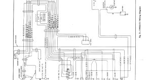
To Properly Read A Wiring Diagram, One Offers To Find Out How Typically The Components Within The System Operate.
See instruction on next page. You will need to set it to i2c mode at the default address of 105 for this project. Pulses of light from an infrared source pass through an optical filter tuned specifically to the co 2 absorption wavelength (λ= 4.2 µm).
Denso 4 Wire O2 Sensor Wiring Diagram By Vallery Masson On June 11, 2021 Injunction Of Two Wires Is Generally Indicated By Black Dot In The Junction Of Two Lines.
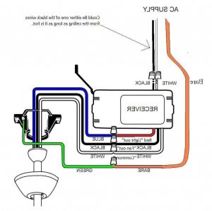
Honeywell co2 sensor wiring diagram. 8001 / 8001b / 8002 / 8002b / 8007 / 8008 installing the sensor notice! An oxygen sensor wiring diagram is a drawing that shows how the oxygen sensor is connected to the vehicle’s electrical system.
By Default, The Co2 Sensor Comes In Uart Mode.
For example , in case a module is usually powered up and it sends out a new. The problem is that the ecm reads voltage from the sensor, any change in resistance through that path can lead to false. Honeywell co2 sensor wiring diagram free download 2022 by kylie.ondricka.
Refer To The Datasheet On How To Change Modes.
These transmitters can be used. Co2 sensor wiring diagram 1999 suburban 7.4 l o2 sensor wiring diagram. Oil/fuel pressure & flex fuel diagram.
[Xc_9832] Co2 Sensor Wiring Diagram.
The diagram will show the location of. Gates | bea americas us.beasensors.com. I recently went to a friends garage to change oil and.