Coverstar Switch Wiring Diagram. Coverstar rocker switch wiring diagram; * the control switch must be mounted in a location where 100% of the pool surface is visible.
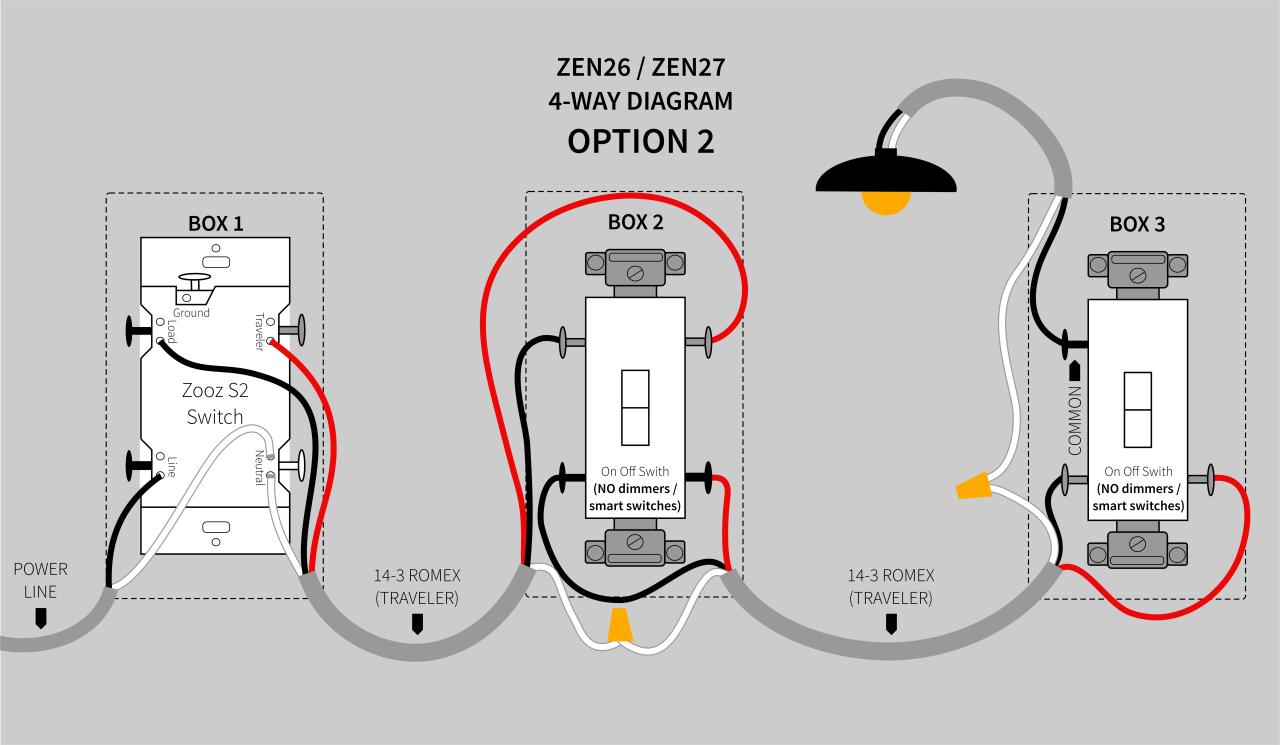
Web electrical wiring and service work should only be performed by a qualified individual. The other wire is to be joined with the white (neutral) wires. A wiring diagram will reveal you where the cables need to be.
Web Wiring The Electrical Switch.
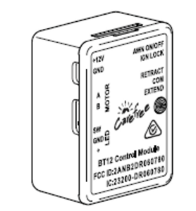
Motor is rated at 8 amps. Web rotary limit wiring diagram note: Wiring the electrical switch options note:
Web There Should Be A Bond Wire Extended From The Equipment Pad To The Cover Box, So It Too Can Be Attached To The Mechanism.
The control switch must be mounted in a fixed. After final wiring, if the cover. * the red and black wires from the motor connect to the directional terminals.
A Wiring Diagram Will Reveal You Where The Cables Need To Be.
Use 15 amp gfci breaker at panel. Web switch should be mounted 5 feet above floor and where operator will have a full view of the pool. The switches are rated at 15 amps for 110 volts.
Connect The Ground Wires From The Power Supply And The Motor Together.
* the control switch must be mounted in a location where 100% of the pool surface is visible. Coverstar rocker switch wiring diagram; The motor and one of the wires.
Web * Use Water Tight Connections At All Wire Junction Locations.
Web coverstar electrical wiring diagram 12.22.20; The top switch is easier to adjust. Contact your coverstar distributor for.