Crankcase Heater Wiring Diagram. The resistance in the heater coil. Take a look at this schematic.
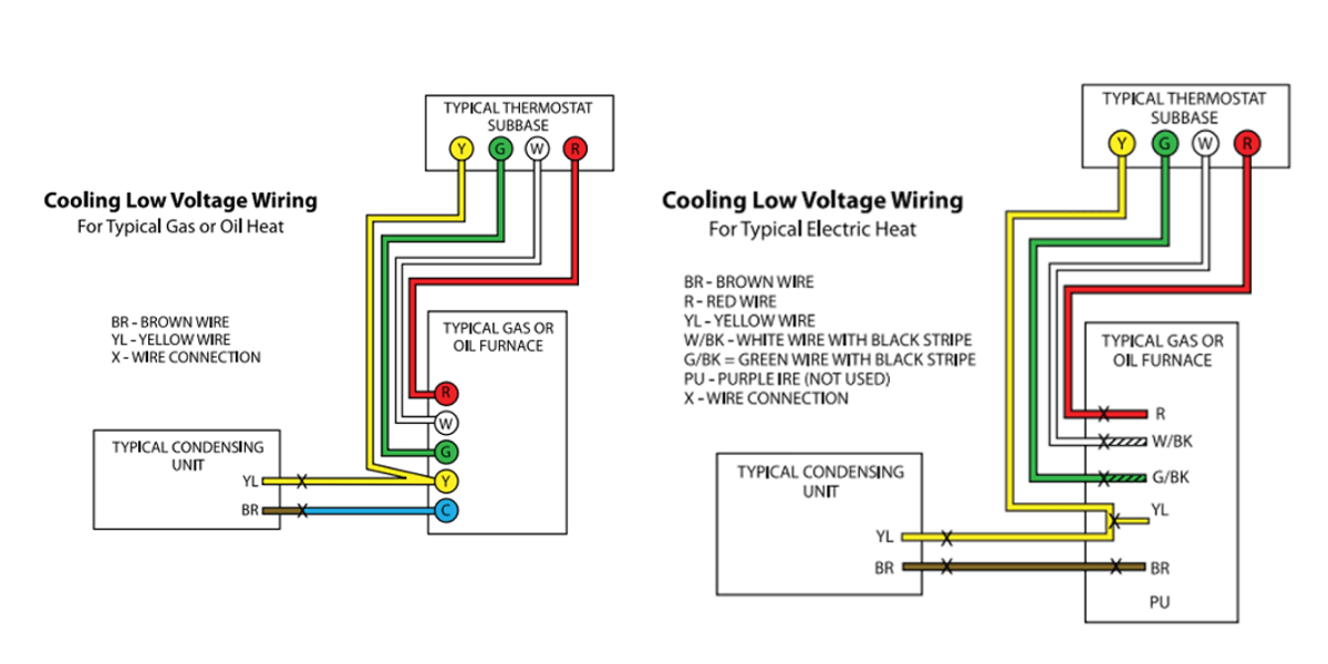
Hvac Low Voltage Wiring Furnace / Room thermostat wiring diagrams for from fredbeattie34.blogspot.com
3 phase 1 500 2490774 valve plate kit w gaskets 1 510 2490785 gasket kit dk* 1 520 2497184 crankcase. A crankcase heater generally has the same electrical symbol as a resistorbecause it converts electricity directly into heat via electrical resistance. These crankcase heaters slid into the compressor sump on the big orange tyler reciprocating compressors.
Shut Off The Power To The Circuit That You’ll Be Working On.
120 volt copeland compressor wiring diagram : Click on add equipment / aux heat source select connection: They use a simple electrical circuit to create heat within the crankcase when the compressor.
Actually, As I Read The Wiring Diagram, It Appears That All Four Of The O2 Sensor Heaters Share The Same Fuse As The Crankcase Vent Or Breather Heater.
These crankcase heaters slid into the compressor sump on the big orange tyler reciprocating compressors. Trane diagram air wiring xe90. 1,910 74 variety of wire crafts.
Luckily, There Are Some Places That May Have Just What You Need.
Select aux1 or aux 2 based on wiring connection to aux heater default: Copeland compressor crankcase heater compressors. Ac service tech llc 219k views 3 years ago hvac compressor crankcase heater wiring grayfurnaceman 22k views 8 years.
A Diagram For An Ac Unit Usually Includes:
Wiring cooling heating thermostat honeywell diagram manual thermostats. Follow these steps to wire your 240 volt garage heater: Chiller trane diagram hvac wiring cooled air chillers heatpump unknown april.
Copeland Crankcase Heater Wiring Diagram Check Carefully For Any Shipping Damage.
Place the wiring diagram provided with the kit on the inside of the control box cover. 120 volt copeland compressor wiring diagram. Take a look at this schematic.